Navigation
Install the app
How to install the app on iOS
Follow along with the video below to see how to install our site as a web app on your home screen.
Note: This feature may not be available in some browsers.
More options
You are using an out of date browser. It may not display this or other websites correctly.
You should upgrade or use an alternative browser.
You should upgrade or use an alternative browser.
DIY Robotic Tester - BoraTronic
- Thread starter Borat
- Start date
- Tagged users None
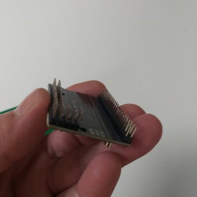
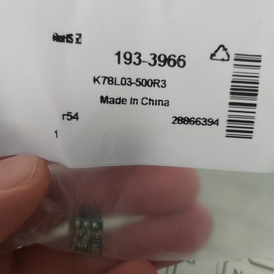
I also bought a couple of 3.3v voltage regulator (PCB has dedicated connectors for it) - these might be used if I am to use a dedicated LED light for RGB sensor.
Also got these tiny 12v fans - 40mmx40mmx10mm, these will be used as stirrer motors. Control of stirrer speed will be achieved by varying voltage supplied to the motors (this is somewhat unconvential - but these are not PWM fans and I know these 12v motors work with lower voltages - they lose torque, but that's exactly what you need to spin the stirrer slower)..
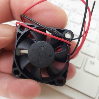

Also got these tiny 12v fans - 40mmx40mmx10mm, these will be used as stirrer motors. Control of stirrer speed will be achieved by varying voltage supplied to the motors (this is somewhat unconvential - but these are not PWM fans and I know these 12v motors work with lower voltages - they lose torque, but that's exactly what you need to spin the stirrer slower)..

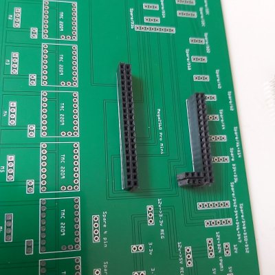
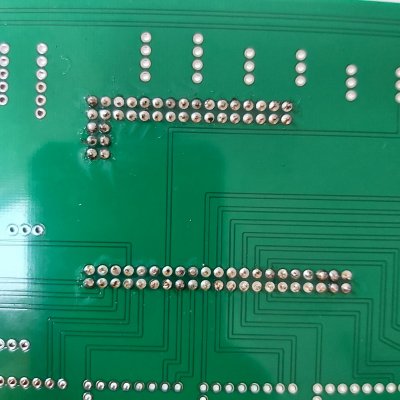
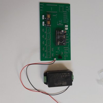
I recevied my PCBs from China that I ordered 5 days ago..
As before - absolutely impressive service (https://jlcpcb.com/):
- delivered by DHL in 2 day's time (from the moment it's been shipped)
- vacuum packaged, with bubble wrap to protect PCBs
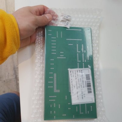
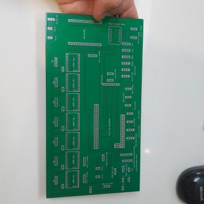
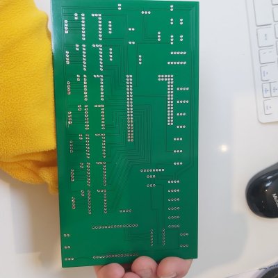
As before - absolutely impressive service (https://jlcpcb.com/):
- delivered by DHL in 2 day's time (from the moment it's been shipped)
- vacuum packaged, with bubble wrap to protect PCBs


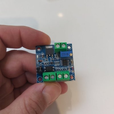
PWM to 0v-10v converter, this will be used to control the stirrer fan speed. As I said previously it's an unconventional way of controlling how fast the fan will rotate - by simply varying the input DC voltage.
I used these chips in my 100w LED fixture build - they have proven to be accurate and reliable. Simply connect this chip to PWM digital pin on your Arduino controller and it will translate PWM duty cycle (0-255) into output voltagae (0v-10v).
I used these chips in my 100w LED fixture build - they have proven to be accurate and reliable. Simply connect this chip to PWM digital pin on your Arduino controller and it will translate PWM duty cycle (0-255) into output voltagae (0v-10v).

Last edited:
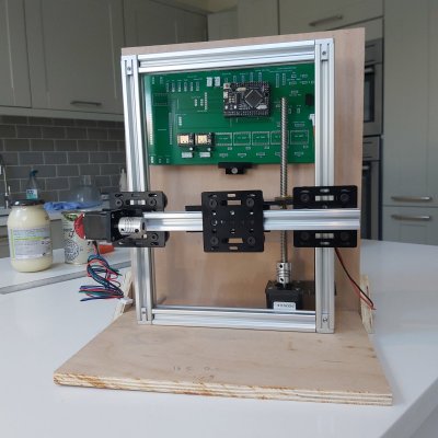
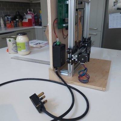
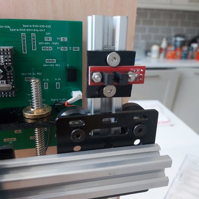
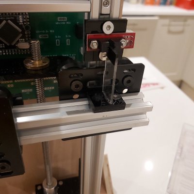
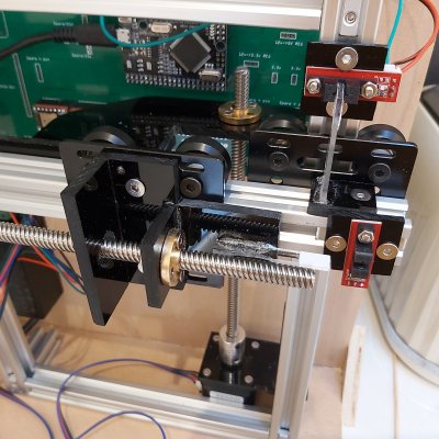
Interestingly - painting acrylic with a marker pen does not block infra-red light to trigger switch sensor event, I had to glue bits of paper instead and it's now working fine... Seems like my PCB is correctly wired - everthing is working as expected, disregard some movement noise - I need to position some components so they run smoother.. I also need to apply a bit of silicone grease to the lead drive. The test runs the rig down (5 turns) and then runs it up until it detects a switch...
Here's the little code sniplet for testing the rig:
Here's the little code sniplet for testing the rig:
Attachments
Last edited:
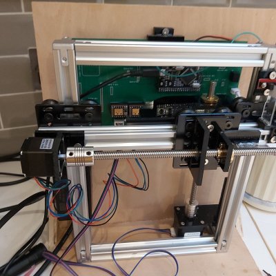
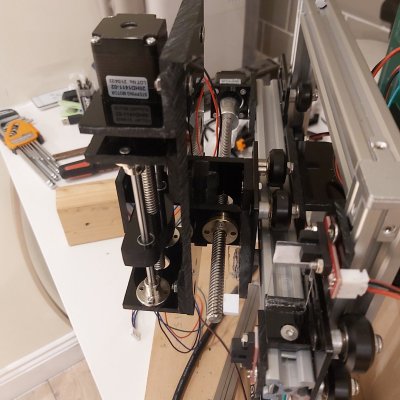
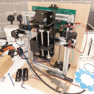
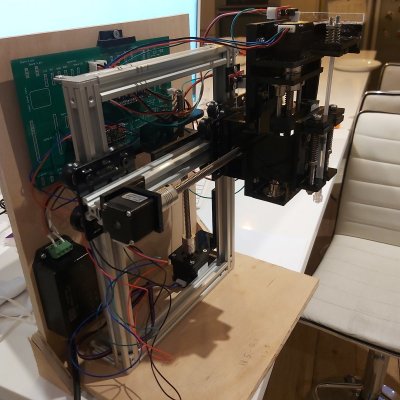
The mechanical part may look quite complicated already - but the code is still very simple/basic..
There is a function that finds zero position - i.e. until optical switch reading becomes zero.. So it turns the respective motor until the optical switch reading becomes zero. If optical switch reading is already zero when the program just started - it turns the motor in the opposite direction (to move the component away from the optical switch) and then starts the search for zero position. Generally these switches seem to be extremely accurate - probably 0.1mm positioning accuracy can be achieved if needed. In reality for this device both vertical and horizonal positioning accuracy of 1mm is sufficient. For syringe actuator - I will need higher accuracy of positining (as accurate as possible)..
Once the zero position has been determined - you can position your motor anywhere along the axis. For example, there will be a hard-coded number of stepper motor turns that need to be performed (such as 5.756 turns) in order to move the gantry plate to where the regant vial is etc.. Stepper motor only needs to find it's zero position once at the start of the programme (and from that point on - it will keep track of its location by counting the number of clock-wise and counter-clock-wise turns).. Having said that if you have tasks that may result in stepper motor losing some steps (e.g. if large load or over-heating) - you can trigger re-positioning of the stepper motor periodically during program execution.
Attachments
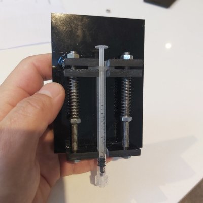
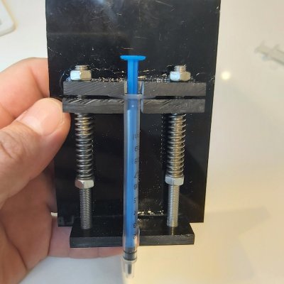
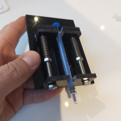
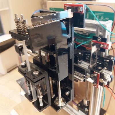
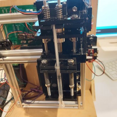
I need to connect the actuator to the syringe holder and add an optical switch - that should be done by weekened and the major mechanical part should be completed.. The only other "mechanical" part remaining would be rotating reagents rack - nothing too complicated but requires good precision of parts..
- Joined
- Nov 7, 2018
- Messages
- 519
- Reaction score
- 309
Wow it is really coming along looks great
Similar threads
- Replies
- 44
- Views
- 2,920
- Replies
- 66
- Views
- 4,500


