What is "Order from Pak" and is it a curse or a treat?Waiting for end Result. May be u get an Order from Pak.
Navigation
Install the app
How to install the app on iOS
Follow along with the video below to see how to install our site as a web app on your home screen.
Note: This feature may not be available in some browsers.
More options
You are using an out of date browser. It may not display this or other websites correctly.
You should upgrade or use an alternative browser.
You should upgrade or use an alternative browser.
DIY Robotic Tester - BoraTronic
- Thread starter Borat
- Start date
- Tagged users None
- Joined
- Jun 7, 2018
- Messages
- 1,050
- Reaction score
- 953
I think he wants to by one from you 
 . So a curse..
I think he wants to buy one from youWhat is "Order from Pak" and is it a curse or a treat?
consider it a treat rom pakistan.What is "Order from Pak" and is it a curse or a treat?
- Joined
- Sep 9, 2019
- Messages
- 193
- Reaction score
- 148
I do not think PWM is a good idea in this context. PWM is OK for the human eye which integrates light over a period of time. But the RGB sensor will pick momentary values, at which time the LED can be either ON or OFF. Therefore you will be measuring erratic values. Taking the average over multiple readings might help a bit, if the interval over which the measurements are accumulated is long enough, but there will be no benefit from using PWM anyway. I think you should use a simple white LED supplied from a stable voltage source through a resistor. Or, if you want to control the current for some reason, use a linear current regulator, not digital. You can find the schematics based on commonly available inexpensive components if you dig the Internet. Or drop me a line if you need help with this.This is very helpful! I will incorporate PWM LED signal for LED when designing connector for RGB sensor (I still have not sent the boards for printing).
May I ask for your advice here:I am currently shining a light through the vial and then using the adafruit rgb sensor on the other side. So far this has given me very good accuracy and reliability when the sensor and led is kept at the same position in a dark housing.
what kind of LED are you using to shine light through vial?
On my PCB design I currently have (a number of) power connectors for 3.3v, 5v and 12v - but I am wondering if I need some other (lower) voltage regulator for this led... The LED does not need to be super-bright, I think something like 1W led would do?
Ok folkes, following my version 1 blunder (some erroneous choice for Arduino Mega 2560 pinout) , I have re-designed the PCB. This time I printed it on a piece of paper and ensured that:
(1) components' pins layout match the design
(2) components do not obstruct each other
This time I also added various redundancy connectors:
(1) additional 5v voltage regulator with output pins
(2) 2x additional 3.3v voltage regulator with output pins (12v->3.3v and 5v->3.3v)
(3) additional unconnected 3 pin and 4 pin connectors
(4) plenty of "spare" connectors, some of which will be used for controlling optical switches to position the rig
PCB is ready for production, I will upload it tonight for printing in China.
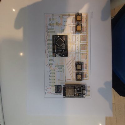

Attachments
bro..
your on another level

your on another level

Indeed I used to follow the dude on utube but he discarded the animals to quick for my taste.I think you should tell the "King of DIY" to step aside on YouTube. Your work amazes me.
No need to discard animals - they can be a tasty snack!!!Indeed I used to follow the dude on utube but he discarded the animals to quick for my taste.
Lol your like a genius clownNo need to discard animals - they can be a tasty snack!!!
- Joined
- Sep 9, 2019
- Messages
- 193
- Reaction score
- 148
1W LED would be way too powerful, you would probably need only 0.1W. But you can use a 1W emitter and drive small current through it - that way it will serve longer and produce much less heat. Forward voltage over white LEDs is about 3V (for good LEDs Vf should be something like 2.6-2.7V, but higher for crappy Chinese LEDs).
So, for 1W LEDs you can drive a current up to 300mA. But if you drive up to 30mA, then it will become 0.1W LED. The 5V supply should be sufficient, but you can also use the 12V supply.
If you want very fine current adjustment and stability, you could use something like LT3092 - but there are no ready-made modules using this chip. Of course, you can design a small PCB for this, but it will probably be an overkill. Providing that your power supplies are stable, I suggest that you use a simple resistor connected in series with the LED. You can calculate its value using Ohm's law: R=(Supply_voltage - LED_voltage)/Desired_current. If using 12V supply, and supposing that your LED Vf is 2.7V, and you want 30mA (0.03A) current, then the required resistance would be (12-2.7)/0.030=310 Ohm. Meaning that you can use a standard 0.5W resistor of either 300 Ohm or 330 Ohm, connected to your 12V supply in series with the LED.
If you want to use the 5V supply, you will need R=(5-2.7)/0.03=76 Ohm, so you can use the nearest standard value of 75 Ohm (next is 82 Ohm and will give you slightly less current). But in case of 5V supply, any voltage instability will result in more variation of current if using this circuit. So, if you go with the current limiting resistor approach, I suggest that you use the 12V supply, and if you want to use the 5V supply, you'd rather use a chip that is capable of precise current regulation (like LT3092 that I have mentioned above)
Last edited:
I am inclined to just use the led onboard the chip: I can make reflective surface on the opposite end easily and see if that' sufficient...1W LED would be way too powerful, you would probably need only 0.1W. But you can use a 1W emitter and drive small current through it - that way it will serve longer and produce much less heat. Forward voltage over white LEDs is about 3V (for good LEDs Vf should be something like 2.6-2.7V, but higher for crappy Chinese LEDs).
So, for 1W LEDs you can drive a current up to 300mA. But if you drive up to 30mA, then it will become 0.1W LED. The 5V supply should be sufficient, but you can also use the 12V supply.
If you want very fine current adjustment and stability, you could use something like LT3092 - but there are no ready-made modules using this chip. Of course, you can design a small PCB for this, but it will probably be an overkill. Providing that your power supplies are stable, I suggest that you use a simple resistor connected in series with the LED. You can calculate its value using Ohm's law: R=(Supply_voltage - LED_voltage)/Desired_current. If using 12V supply, and supposing that your LED Vf is 2.7V, and you want 30mA (0.03A) current, then the required resistance would be (12-2.7)/0.030=310 Ohm. Meaning that you can use a standard 0.5W resistor of either 300 Ohm or 330 Ohm, connected to your 12V supply in series with the LED.
- Joined
- Sep 9, 2019
- Messages
- 193
- Reaction score
- 148
Yes, you can do that, and it will probably work. But the detector will also catch the reflected light from the vial wall - and that light has not passed through the solution. Yes, you can use cancellation for this, as it will probably be a constant, but it will reduce the dynamic range. In my opinion, moving the LED to the opposite side to the detector is a better approach. But of course, you may start it as you mentioned, and then can fetch another LED on the opposite side at a later point.I am inclined to just use the led onboard the chip: I can make reflective surface on the opposite end easily and see if that' sufficient...
Similar threads
- Replies
- 44
- Views
- 2,920
- Replies
- 66
- Views
- 4,500


