DIY Robotic Tester - BoraTronic

dadarara

Community Member
View Badges
Joined
Nov 16, 2020
Messages
88
Reaction score
38
Location
Israel
Rating - 0%
0   0   0
Quick question:
would it make economical sense in using the measurement part of this build (the light led sensor and the Arduino to control it) instead of buying the Hanna testers for alkalinity, magnezium, calcium ?
Obviously the tests will have to be done manually. Fill the bottle with water, fill it with reagent and push it into the above unit. (basically the same as Hanna units)
Should I invest time and money , considering the end result accuracy and other parameters ?
 
OP
OP
Borat

Borat

Valuable Member
View Badges
Joined
Apr 4, 2021
Messages
1,569
Reaction score
1,878
Location
United Kingdom
Rating - 0%
0   0   0
Quick question:
would it make economical sense in using the measurement part of this build (the light led sensor and the Arduino to control it) instead of buying the Hanna testers for alkalinity, magnezium, calcium ?
Obviously the tests will have to be done manually. Fill the bottle with water, fill it with reagent and push it into the above unit. (basically the same as Hanna units)
Should I invest time and money , considering the end result accuracy and other parameters ?
I don't know the answer to this question - but I have seen a some threads where people tried to build their own colourimeters. To me that would make perfect sense - especially that where the is a colour palette provided, I am usually unable to match the colour to determine concentration (e.g. Red Sea Nitrate).

I use Hanna ULR Phosphorus for phosphate testing currently - the colour is subtle but quite readable even to the eye (well - as soon as your phosphates are 0.1ppm and more), I always know the approximate result by just looking at the amount of blue colour in the vial.. So a colourimeter should be kind of a universal device really consisting of exactly that - arduino and colour sensor (and maybe a small LED screen).
 
OP
OP
Borat

Borat

Valuable Member
View Badges
Joined
Apr 4, 2021
Messages
1,569
Reaction score
1,878
Location
United Kingdom
Rating - 0%
0   0   0
I decided to use a simple swtich sensor for rotating rack...

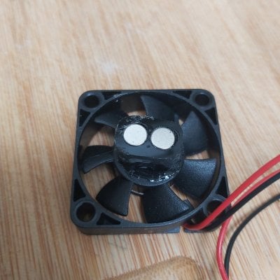
I also tested the strength of magnets in the stirrer motor - these seem to be sufficiently strong given about 10mm distance they need to overcome (2mm clearance + 5mm acrylic + 3mm glass) ..

20220402_120732.jpg

20220402_120744.jpg

I now need to wait for glue to set - before I can start mounting the stirrer..
 

iLMaRiO

Well-Known Member
View Badges
Joined
Jun 24, 2020
Messages
601
Reaction score
132
Rating - 0%
0   0   0
Maybe i've missed the explaination but..................................... how do you read the test response ? Are you automating just the test procedure but leaving the response reading to the operator ?
 
OP
OP
Borat

Borat

Valuable Member
View Badges
Joined
Apr 4, 2021
Messages
1,569
Reaction score
1,878
Location
United Kingdom
Rating - 0%
0   0   0
Maybe i've missed the explaination but..................................... how do you read the test response ? Are you automating just the test procedure but leaving the response reading to the operator ?
Everything will be automated. This is just about 40% of the project.

I still need to add these key ingredients:
- reagent vial with stirrer
- 4x stepper motors with dosing heads
- color sensor (and a few bits and pieces)
 

iLMaRiO

Well-Known Member
View Badges
Joined
Jun 24, 2020
Messages
601
Reaction score
132
Rating - 0%
0   0   0
Everything will be automated. This is just about 40% of the project.

I still need to add these key ingredients:
- reagent vial with stirrer
- 4x stepper motors with dosing heads
- color sensor (and a few bits and pieces)
did you think how to calibrate the color sensor ? How do you know that color X equals to a defined amount of ppm ? Each vendor uses different reagents.... There isn't a standard one.
 
OP
OP
Borat

Borat

Valuable Member
View Badges
Joined
Apr 4, 2021
Messages
1,569
Reaction score
1,878
Location
United Kingdom
Rating - 0%
0   0   0
did you think how to calibrate the color sensor ? How do you know that color X equals to a defined amount of ppm ? Each vendor uses different reagents.... There isn't a standard one.
of course i will have to calibrate the colour/concentration curve.

i dont think that will be difficult though..
 

iLMaRiO

Well-Known Member
View Badges
Joined
Jun 24, 2020
Messages
601
Reaction score
132
Rating - 0%
0   0   0
of course i will have to calibrate the colour/concentration curve.

i dont think that will be difficult though..
Interesting. How do you get the curve ? Assuming that will be a linear curve and not a logaritmic one, I think you need some info from the vendor of the test you'll use (and I dubt the vendor will provide you tech info that could be used even by their competitors)

Anyway, good luck and good work. it looks awesome
 
OP
OP
Borat

Borat

Valuable Member
View Badges
Joined
Apr 4, 2021
Messages
1,569
Reaction score
1,878
Location
United Kingdom
Rating - 0%
0   0   0
Now I potentially need to solder a basic PCB, because the mini-fan requires the PWM-to-10V translator in order to control its spin speed. Other components (servo and switch) just require a connector.
 
OP
OP
Borat

Borat

Valuable Member
View Badges
Joined
Apr 4, 2021
Messages
1,569
Reaction score
1,878
Location
United Kingdom
Rating - 0%
0   0   0
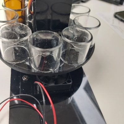
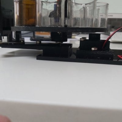
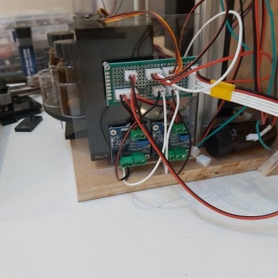
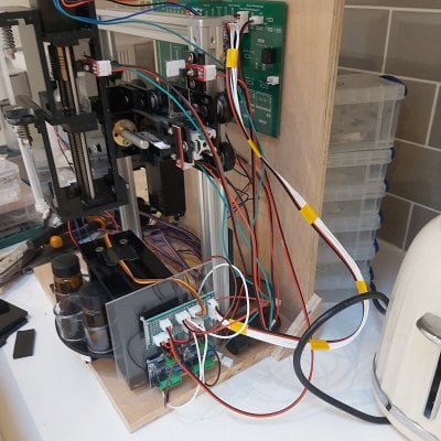
I completed the wiring part for the reagent rack component and the second stirrer that is yet to be built (cables in the picture are a bit of a mess - because most cables are disconnected and are hanging loose) - but still haven't had time to test it yet. I can tidy up cable lengths much later - when I know the exact placement of each component, for now the cables are a bit longer than needed.


20220404_191410.jpg

20220404_191400 (1).jpg
 
OP
OP
Borat

Borat

Valuable Member
View Badges
Joined
Apr 4, 2021
Messages
1,569
Reaction score
1,878
Location
United Kingdom
Rating - 0%
0   0   0
A few small hickups:
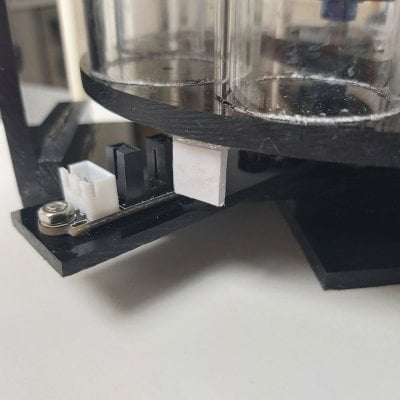
- the optical endstop switch that I mounted on the reagent rack is faulty, I ordered a couple of replacement switches but it will take a couple of days to receive those
- the "continous rotation servo motor" is actually not a servo motor at all (but just a motor where you can approximately control the rotation speed), luckily I am not relying on the motor being "servo" and instead using the endstop switch for positioning.
Now I will need to slightly re-work the bottom of the reagent rack by gluing endstop triggering fins for each of the 9 reagent holders (I am going to make one of the fins a bit longer than others - so I can know which of the 9 vials is near the endstop).

I will give you an update once I have those parts and can finish testing the reagent rack assembly.
 

KonradTO

Valuable Member
View Badges
Joined
Aug 11, 2021
Messages
1,254
Reaction score
702
Location
Germany
Rating - 0%
0   0   0
A few small hickups:
- the optical endstop switch that I mounted on the reagent rack is faulty, I ordered a couple of replacement switches but it will take a couple of days to receive those
- the "continous rotation servo motor" is actually not a servo motor at all (but just a motor where you can approximately control the rotation speed), luckily I am not relying on the motor being "servo" and instead using the endstop switch for positioning.
Now I will need to slightly re-work the bottom of the reagent rack by gluing endstop triggering fins for each of the 9 reagent holders (I am going to make one of the fins a bit longer than others - so I can know which of the 9 vials is near the endstop).

I will give you an update once I have those parts and can finish testing the reagent rack assembly.
Why don't you use a color sensor as well for the "start" position of the rack? You could place a white adhesive circle below and it should be easy for the sensor to find the right position then.
I am planning to build something similar soon, my idea was to do something like you are doing (with a circular rack, I got the idea from another automatic tester some guy built for a school project) but with peristaltic pumps only instead.
 

KonradTO

Valuable Member
View Badges
Joined
Aug 11, 2021
Messages
1,254
Reaction score
702
Location
Germany
Rating - 0%
0   0   0
Why don't you use a color sensor as well for the "start" position of the rack? You could place a white adhesive circle below and it should be easy for the sensor to find the right position then.
I am planning to build something similar soon, my idea was to do something like you are doing (with a circular rack, I got the idea from another automatic tester some guy built for a school project) but with peristaltic pumps only instead.
Also there could be a different color for each vial, so you can double check:
1) rotations from start position until desired vial
2) check if color matches
 

dadarara

Community Member
View Badges
Joined
Nov 16, 2020
Messages
88
Reaction score
38
Location
Israel
Rating - 0%
0   0   0
I am wondering why the colorimetric method that Hanna checkers are using is not an easier choice ?
I mean fill 10ml water vial than add a precise measure of reagent and check the color with something like AS7341 Spectral Color Sensor. can test Nitrit, Nitrat, ALkalinity , Magnezium , Phosphate and maybe some more. per what Hanna have the checkers for...
 
Last edited:
OP
OP
Borat

Borat

Valuable Member
View Badges
Joined
Apr 4, 2021
Messages
1,569
Reaction score
1,878
Location
United Kingdom
Rating - 0%
0   0   0
I had to pause the project as I was preparing to move the house.. slowly getting back to it..

The servo motors are a no-no-no for any of my future projects, they an utter piece of inferior potassium. I am going to redo the reagent rack with a stepper motor, I don't have the space for this driver on the PCB (only 7 steppers were planned) but I can still connect the 8th stepper motor using spare connectors I allowed for..
 
OP
OP
Borat

Borat

Valuable Member
View Badges
Joined
Apr 4, 2021
Messages
1,569
Reaction score
1,878
Location
United Kingdom
Rating - 0%
0   0   0
Here are some updates for you folkes: where I left the project was the reagent rack: basically servo motors are a piece of inferior potassium (aka crap) and I decided to use a small stepper motor instead.

One problem however was that I initially only allowed for 7 stepper motors on my PCB and that does not have any spares to use... So as I was in the process of redesigning some of my DIY tools I used the chance to redesign my existing BoratTronic PCB and order it from China anew. As before it's a very simple and intuitive PCB that even a 5 year old will understand NOT..

Changes to the previous PCB version are as follows:
- I fixed a few small bugs (2 missing traces to pins - only one was critical : the 7th motor driver didn't have one of the required trace)
- I added a connector for 12v PWM fan control (via pin 9 - which is a somewhat special pin)
- I added the 8th TMC 2209 stepper motor driver to the PCB

One other thing I did was to test the existing PCB, espeically connectivity between Arduino Mega 2560 and ESP32 chips: it took me awhile to figure this out - but it's now all working smoothly (which meams the complex connection via logic level converter chip is all done correctly!). I will order my batch of PCBs in the next few days and hopefully I will have then about a week later..
 
Back
Top