I'm afraid that the board somehow broke. Like a capacitor or resistor fell off when I put it away or something. It's so odd. It's not the network for sure because everything else was working perfectly. Even the ethernet wasn't working since I have a pi 3.Do you have a build thread? If raspberry pi is going out of network then its something to do with network setup or router/gateway being flaky, something beyond reef-pi. But this can definitely be addressed. When I used to run reef-pi controllers in my Comcast /xfinity home network it used to be a common problem, so much so I deployed a nightly cron job to just restart wifi network on every pi. For the last one year, I have google wifi network that segregates the IoT devices in their own network, and that has fixed it.
There are many otherways to workaround this problem (like deploying some hourly script that checks for network and then restart it when needed), you can try those, as well as finding out whats happening exactly and solve it at the root
Navigation
Install the app
How to install the app on iOS
Follow along with the video below to see how to install our site as a web app on your home screen.
Note: This feature may not be available in some browsers.
More options
You are using an out of date browser. It may not display this or other websites correctly.
You should upgrade or use an alternative browser.
You should upgrade or use an alternative browser.
reef-pi :: An opensource reef tank controller based on Raspberry Pi.
- Thread starter Ranjib
- Start date
-
- Tags
- controller raspberry-pi
- Tagged users Ranjib
Happy new year everyone 
Too much tech talks..
Zoa/Lords are fighting for real estate

During last week's water change, i broke a large chunk of red dragon colony :-/ . Otherwise its doing good,

The pico tanks are humming along,

Gpniopora, I think its being stung by the challice underneath.. i am thinking of relocating it, but dont know where

Ricordia . gorgeous as always

Zoa/Lords are fighting for real estate
During last week's water change, i broke a large chunk of red dragon colony :-/ . Otherwise its doing good,
The pico tanks are humming along,
Gpniopora, I think its being stung by the challice underneath.. i am thinking of relocating it, but dont know where
Ricordia
- Joined
- Dec 16, 2018
- Messages
- 1,189
- Reaction score
- 2,826
Im about to install a big sump on my FW planted and its hard knowing I could easily go SW at anytime after that.Too much tech talks..
Zoa/Lords are fighting for real estate

During last week's water change, i broke a large chunk of red dragon colony :-/ . Otherwise its doing good,

The pico tanks are humming along,

Gpniopora, I think its being stung by the challice underneath.. i am thinking of relocating it, but dont know where

Ricordia. gorgeous as always

Pics like this DO NOT help!!! Lol
Very beautiful!!!
Hey all,
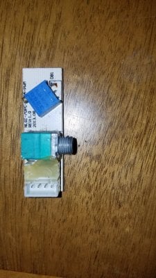
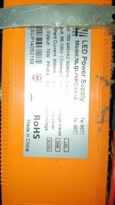
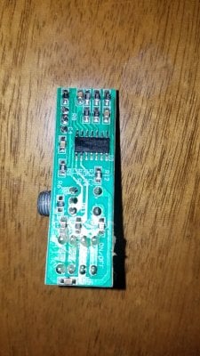
I've got a ML goby hat and a just might a no name black box (used) that in trying to set up here. The dimmer boards are showing 4 wires: an on/off, a +12v, a PWM, and a GND. How do I wire these into the goby? I'm pretty sure I can just go directly to the "light 1" just since this is pwm and not analog, but not sure which wire to put where.

Also, should I put the power cords in the adj or is it okay to just dim to 0 and leave them powered on?
I've got a ML goby hat and a just might a no name black box (used) that in trying to set up here. The dimmer boards are showing 4 wires: an on/off, a +12v, a PWM, and a GND. How do I wire these into the goby? I'm pretty sure I can just go directly to the "light 1" just since this is pwm and not analog, but not sure which wire to put where.
Also, should I put the power cords in the adj or is it okay to just dim to 0 and leave them powered on?
Hey all,
I've got a ML goby hat and a just might a no name black box (used) that in trying to set up here. The dimmer boards are showing 4 wires: an on/off, a +12v, a PWM, and a GND. How do I wire these into the goby? I'm pretty sure I can just go directly to the "light 1" just since this is pwm and not analog, but not sure which wire to put where.

Also, should I put the power cords in the adj or is it okay to just dim to 0 and leave them powered on?
Is there a knob or just an on/off switch? Both?
This may be similar to the way Viparspectra lights work, where we have gnd-pwm-12v-on/off. Not sure if your drivers are 5v or 10v PWM, but the way Vipars work, the GND and PWM from HAT Light1 will work for dimming, that's the easy part. Then the driver needs to be told to turn on or off, this is done by essentially shorting 12v and on/off when you turn the knob on your light fixture. The way I and some others have tackled this in ReefPi was to use the ULN2803 on the HAT, to toggle a 12v relay (as a switch) to turn on and off the driver; this needs to be repeated per channel, per fixture....so for a single fixture you would need 2 channel relays (for 2 fixtures a 4 channel relay etc).
- Joined
- Jul 1, 2019
- Messages
- 688
- Reaction score
- 925
Beal, I think you need one of these:

 www.tindie.com
The Govy converts to 0-3.3v and the converter takes those and multiplies it to 0-10v for the dimming function.

PWM Converter for Mars Aqua by ML Reefkeeping on Tindie
Control Mars Aqua LED lights with PWM
I think you're probably right. It was throwing me off because the dimmer board labels are a little unusualBeal, I think you need one of these:
The Govy converts to 0-3.3v and the converter takes those and multiplies it to 0-10v for the dimming function.
PWM Converter for Mars Aqua by ML Reefkeeping on Tindie
Control Mars Aqua LED lights with PWMwww.tindie.com
What if I buy new drivers... They're pretty cheap, right? Maybe I can buy a pair of drivers that take the 3.3v pvm directly?
Quick question. Building a separate reef-pi to do a 12V LED strip and 4 dosing pumps. I have wired several together but have never used the PCA9685 and upon reviewing the lighting guide I got very stumped at the "pin 12 on the PCA9685" but it is clearly hooked up to Pin/jack 6. I can't get my setup to work and was wondering if this is a factor. Can someone possibly explain this?
Quick question. Building a separate reef-pi to do a 12V LED strip and 4 dosing pumps. I have wired several together but have never used the PCA9685 and upon reviewing the lighting guide I got very stumped at the "pin 12 on the PCA9685" but it is clearly hooked up to Pin/jack 6. I can't get my setup to work and was wondering if this is a factor. Can someone possibly explain this?
I assume that it's referring to physical pin 12, which is routed to LED 6. Here's the pinout diagram for the actual PCA9685 chip. What section in the lighting guide are you referring to? I couldn't find it.
But if defining a doser in the tab then I can setup the PWM board and specify my jacks (pins 0-3 on the PCA9685). In the dosing tab I would just the Jack and pin from the board. So for my first pump its connected to pin 0 on the PWM board so I have Jack 0 and Pin 0. Not sure when to use the pin # as defined by the datasheet.
What if I buy new drivers... They're pretty cheap, right? Maybe I can buy a pair of drivers that take the 3.3v pvm directly?
The Mars Aqua boards are only $15, I think they'd still be cheaper:

PWM Converter for Mars Aqua by ML Reefkeeping on Tindie
Control Mars Aqua LED lights with PWM
But if defining a doser in the tab then I can setup the PWM board and specify my jacks (pins 0-3 on the PCA9685). In the dosing tab I would just the Jack and pin from the board. So for my first pump its connected to pin 0 on the PWM board so I have Jack 0 and Pin 0. Not sure when to use the pin # as defined by the datasheet.
I may be mis-reading what you're saying, but I'll give it a shot.
When you're setting up a dosing pump, the Jack & Pin number are going to be the same. I don't think there's anywhere you actually need to use the physical pin# in Reef Pi for the PCA9685. Without seeing the portion of the guide you're referring to, I can't say for sure. But I think the reference to Pin 12 on the PCA9685 was just a mixup in naming. I know I've done it multiple times going back & forth between physical & GPIO pinos on the Pi itself.
Kinda at a loss and broke reef-pi by changing the driver board name so I am doing a clean install. From the other threads I have read the default i2c address should be 64 for the PCA9685 but when I run i2cdetect I was seeing two separate addresses 0x40 and 0x70 (tried the default as well). I think this may be my issue but after trying both of these I still cant get it to work. Looking at the error log I found this
Jan 01 19:41:41 raspberrypi reef-pi[312]: 2020/01/01 19:41:41 ERROR: lighting-subsystem: Failed to set pwm value. Error: pin 4 on jack 5 has no driver: driver 2 for jack BlueLight not found: driver by id 2 not available
and after changing the address I would get {error:Failed to update. Error: invalid pin 0: driver 2 for jack Pump1 not found: driver by id 2 not available} when I went to re-save the jack in the connector tab.
0x40 and 0x70 is normal, 0x40 or 64 in decimal is the address you want to use to create new driver.then create a jack and associate it with the new driver. And then create light and associate it with the newly created jack. 0x70 is all call address used to set pwm values for all pins at once. We don’t use it in reef-piKinda at a loss and broke reef-pi by changing the driver board name so I am doing a clean install. From the other threads I have read the default i2c address should be 64 for the PCA9685 but when I run i2cdetect I was seeing two separate addresses 0x40 and 0x70 (tried the default as well). I think this may be my issue but after trying both of these I still cant get it to work. Looking at the error log I found this
Jan 01 19:41:41 raspberrypi reef-pi[312]: 2020/01/01 19:41:41 ERROR: lighting-subsystem: Failed to set pwm value. Error: pin 4 on jack 5 has no driver: driver 2 for jack BlueLight not found: driver by id 2 not available
and after changing the address I would get {error:Failed to update. Error: invalid pin 0: driver 2 for jack Pump1 not found: driver by id 2 not available} when I went to re-save the jack in the connector tab.
... From the other threads I have read the default i2c address should be 64 for the PCA9685 but when I run i2cdetect I was seeing two separate addresses 0x40 and 0x70 (tried the default as well)...
0x40 is the address in hexadecimal format. That converts to 64 in decimal, which is what you should enter. When you get your clean install up & going, try 64 as the address. If it's seeing 0x40, you're good to go.
EDIT: Ranjib beat me to it by seconds & in more detail, lol.
- Joined
- Dec 24, 2019
- Messages
- 133
- Reaction score
- 200
Kinda at a loss and broke reef-pi by changing the driver board name so I am doing a clean install. From the other threads I have read the default i2c address should be 64 for the PCA9685 but when I run i2cdetect I was seeing two separate addresses 0x40 and 0x70 (tried the default as well). I think this may be my issue but after trying both of these I still cant get it to work. Looking at the error log I found this
Jan 01 19:41:41 raspberrypi reef-pi[312]: 2020/01/01 19:41:41 ERROR: lighting-subsystem: Failed to set pwm value. Error: pin 4 on jack 5 has no driver: driver 2 for jack BlueLight not found: driver by id 2 not available
and after changing the address I would get {error:Failed to update. Error: invalid pin 0: driver 2 for jack Pump1 not found: driver by id 2 not available} when I went to re-save the jack in the connector tab.
No need to do complete rebuild, just delete the reef-pi.db file and you should be fine with all defaults back.
Troubleshooting | reef-pi - An opensource reef tank controller based on Raspberry Pi
Check if reef-pi is running sudo systemctl status reef-pi.service Check for errors in log sudo journalctl -fu reef-pi.service Connecting reef-pi using a TTL cable. Adafruit has an excellent tutorial on how to use USB TTL cable to configure raspberry pi, in cases where display and keyboard...
- Joined
- Dec 24, 2019
- Messages
- 133
- Reaction score
- 200
basically here is how you need to wire it up.I assume that it's referring to physical pin 12, which is routed to LED 6. Here's the pinout diagram for the actual PCA9685 chip. What section in the lighting guide are you referring to? I couldn't find it.

If your light is using 4 channels assign LED0 through LED3 for light control and if you want to control pwm doser with two pumps connect to next available pins i.e. LED4 and LED5. Or if you want to give yourself options for growth on the light start assigning light from LED0, LED1, etc and your doser from the back i.e LED15,LED14 etc
Similar threads
- Replies
- 2
- Views
- 252
- Shipping Available
- Replies
- 2
- Views
- 225


