reef-pi :: An opensource reef tank controller based on Raspberry Pi.

OP
OP
Ranjib

Ranjib

7500 Club Member
View Badges
Joined
Apr 16, 2016
Messages
9,848
Reaction score
17,081
Location
Pleasant Hill, Concord
Rating - 0%
0   0   0
Steppers would be nice but not necessary. Invest in a good peralistic pump head. Here is what I am using with l298n
I did change the dc motors from the originals to slower speeds and so far with all my testing I should be able to dose in 0.2ml increments if desired. Timing pumps in 0.2sec for duration. Yes they are big but flawless. Got them on ebay 2 years ago. Had them running with Arduino now converting to Reef-Pi.

1577769393353.png
agree they are pretty good and affordable alternative. but i doubt they can be as precise as stepper motors, which is what we need for very precise volume dosing to experiment with things involving titration, other than general dosing.
In fact after running ATO via DC motor based peristaltic pumps and using tropical marine all in one, i think i will not need stepper based dosing pumps purely for dosing regimen. The ATO based dosing is pretty effective when I know whats my ATO consumption at weekly cadence
 

BenB

Active Member
View Badges
Joined
Jun 11, 2019
Messages
112
Reaction score
155
Rating - 0%
0   0   0
agree they are pretty good and affordable alternative. but i doubt they can be as precise as stepper motors, which is what we need for very precise volume dosing to experiment with things involving titration, other than general dosing.
In fact after running ATO via DC motor based peristaltic pumps and using tropical marine all in one, i think i will not need stepper based dosing pumps purely for dosing regimen. The ATO based dosing is pretty effective when I know whats my ATO consumption at weekly cadence

The L293D can drive stepper motors:
 

pies666

New Member
View Badges
Joined
Nov 25, 2019
Messages
12
Reaction score
9
Rating - 0%
0   0   0
Heya,

Quick question regarding Water Level Controller Guide on adafruit. The DFRobot Water sensor data output is connected directly to Rpi's GPIO pin. As this sensor is powered by 5V, high level output will be somewhere around 4.5-4.7V. As far as I know such a high voltage is not really safe for raspberry. Shoundn't it be used with some sort of 5V-3.3V level shifter instead?

Analog input in Reef-Pi is just for 3rd party (non Atlas Scientific) PH meter - am I right?

Happy New Year everyone!
 

Bigtrout

Valuable Member
View Badges
Joined
Dec 16, 2018
Messages
1,189
Reaction score
2,826
Rating - 0%
0   0   0
yeah, im not sure if we can use pwm signals as it is. I am looking at common stepper driver codes right now, theres stuff like single phase, dual phase, micro-stepping etc with some precise time related code. there are options for passing pwm signal directly to stepper drivers, but it still involves some directional controls similar to l293d (h bridge). i'll keep you all posted, my goal is to do whatever required to get a nema 17 style peristaltic pump working with reef-pi.
@Ranjib
Look into the a4988 stepper driver. It allows precise control of a nema17 stepper with just 2 pins of an arduino. It offers alot including ovetcurrent protection and precise signal decay rates and may be the ticket. Its affordable and comes on a breakout board.
It allows more precise control than a l298 driver. The l293 or l298 drivers are meant for a regular DC motor. Although they work they are inefficient and do not allow proper precise control of a stepper motor.
The A4988 is a priper stepper control. The current limiting key. With a resistor you set the current limit of the driver. The driver sends current up to that limit to the stepper as quick as possible this allows fast precise movement of the motor. The a4988 also allows incremental step control.

If the goal for reef-pi is to control a nema17 stepper head for a precise doser then this is the chip to do it precisely and safely.

Heres some info on using an arduino to do it
 
Last edited:

Phildago

Well-Known Member
View Badges
Joined
Oct 11, 2019
Messages
854
Reaction score
933
Location
Broad Channel
Rating - 0%
0   0   0
Steppers would be nice but not necessary. Invest in a good peralistic pump head. Here is what I am using with l298n
I did change the dc motors from the originals to slower speeds and so far with all my testing I should be able to dose in 0.2ml increments if desired. Timing pumps in 0.2sec for duration. Yes they are big but flawless. Got them on ebay 2 years ago. Had them running with Arduino now converting to Reef-Pi.

1577769393353.png

Im just trying to scrounge and recycle anything I can to save some money while making this as consistent as possible.

So far my doser is reliable, so switching it over to reef pi will likely make no difference in the reliability, just add convenience.

That pump head looks awesome, do you remember what it was called or listed under? Just for future reference if any of my pump heads fail
 

marekd1

Active Member
View Badges
Joined
Dec 24, 2019
Messages
133
Reaction score
200
Rating - 0%
0   0   0
Im just trying to scrounge and recycle anything I can to save some money while making this as consistent as possible.

So far my doser is reliable, so switching it over to reef pi will likely make no difference in the reliability, just add convenience.

That pump head looks awesome, do you remember what it was called or listed under? Just for future reference if any of my pump heads fail

You can find them on EBAY, under … "12V 400ml/min Peristaltic Pump Dosing Pump Vacuum Aquarium Lab Analytical Water" just remember they are high flow so you will need to slow them down by changing the DC motor to say 10 rev/min if you want 0.2 ml per dose, then the rest of magic will happen with reef-pi. If you want to dose minimum 1ml per dose then no need to make changes. Reef-Pi can control it at 80% 0.3 sec for 0.5 ml per dose. At least this is what my testing concluded so far.

Nice thing about this head is that its using slotted shaft on the motor so there is way for the slippage and center hub is fitted in the bearing. Its very, very accurate.
 

marekd1

Active Member
View Badges
Joined
Dec 24, 2019
Messages
133
Reaction score
200
Rating - 0%
0   0   0
Last edited:

Phildago

Well-Known Member
View Badges
Joined
Oct 11, 2019
Messages
854
Reaction score
933
Location
Broad Channel
Rating - 0%
0   0   0
You can find them on EBAY, under … "12V 400ml/min Peristaltic Pump Dosing Pump Vacuum Aquarium Lab Analytical Water" just remember they are high flow so you will need to slow them down by changing the DC motor to say 10 rev/min if you want 0.2 ml per dose, then the rest of magic will happen with reef-pi. If you want to dose minimum 1ml per dose then no need to make changes. Reef-Pi can control it at 80% 0.3 sec for 0.5 ml per dose. At least this is what my testing concluded so far.

Nice thing about this head is that its using slotted shaft on the motor so there is way for the slippage and center hub is fitted in the bearing. Its very, very accurate.
Excellent. I'd be dosing 1 ml at a time so it's good to go out of the box for me. Thanks
 

marekd1

Active Member
View Badges
Joined
Dec 24, 2019
Messages
133
Reaction score
200
Rating - 0%
0   0   0
it will do both DC and steppers. 2 DC motors per board or 1 stepper
Heya,

Quick question regarding Water Level Controller Guide on adafruit. The DFRobot Water sensor data output is connected directly to Rpi's GPIO pin. As this sensor is powered by 5V, high level output will be somewhere around 4.5-4.7V. As far as I know such a high voltage is not really safe for raspberry. Shoundn't it be used with some sort of 5V-3.3V level shifter instead?

Analog input in Reef-Pi is just for 3rd party (non Atlas Scientific) PH meter - am I right?

Happy New Year everyone!

the voltage will not be 5V as there will be a drop on the junction but still might be little too high for my liking so I would use level shifter or Michael has rather elegant solution that you can adopt, Zener will do the trick to keep the voltage at 3.3V max .... ( your connection point input would be where the switch is.)

1577808090104.png
 
OP
OP
Ranjib

Ranjib

7500 Club Member
View Badges
Joined
Apr 16, 2016
Messages
9,848
Reaction score
17,081
Location
Pleasant Hill, Concord
Rating - 0%
0   0   0
Heya,

Quick question regarding Water Level Controller Guide on adafruit. The DFRobot Water sensor data output is connected directly to Rpi's GPIO pin. As this sensor is powered by 5V, high level output will be somewhere around 4.5-4.7V. As far as I know such a high voltage is not really safe for raspberry. Shoundn't it be used with some sort of 5V-3.3V level shifter instead?

Analog input in Reef-Pi is just for 3rd party (non Atlas Scientific) PH meter - am I right?

Happy New Year everyone!
There’s a dfrobot board in between that interfaces pi gpio /5v with the sensor
 
OP
OP
Ranjib

Ranjib

7500 Club Member
View Badges
Joined
Apr 16, 2016
Messages
9,848
Reaction score
17,081
Location
Pleasant Hill, Concord
Rating - 0%
0   0   0
@Ranjib
Look into the a4988 stepper driver. It allows precise control of a nema17 stepper with just 2 pins of an arduino. It offers alot including ovetcurrent protection and precise signal decay rates and may be the ticket. Its affordable and comes on a breakout board.
It allows more precise control than a l298 driver. The l293 or l298 drivers are meant for a regular DC motor. Although they work they are inefficient and do not allow proper precise control of a stepper motor.
The A4988 is a priper stepper control. The current limiting key. With a resistor you set the current limit of the driver. The driver sends current up to that limit to the stepper as quick as possible this allows fast precise movement of the motor. The a4988 also allows incremental step control.

If the goal for reef-pi is to control a nema17 stepper head for a precise doser then this is the chip to do it precisely and safely.

Heres some info on using an arduino to do it
I’ll check it out ,
 

BenB

Active Member
View Badges
Joined
Jun 11, 2019
Messages
112
Reaction score
155
Rating - 0%
0   0   0
I will give you example with my feeder testing. In order to make it work I had to use DOSER configuration option. This is fine from the function subset perspective but then the label on the Menu bar could not be changed to reflect say Feeder. So it would be nice if you could select the desired operational functions and assign devices Inlets, Outlets, Jacks, etc to a operational role. So just expand what you are already doing with Inlets, Outlets, Jacks but to the menu label.

Additionaly the ability to ad tabs will be welcome. Maybe in the setting tab that you can choose what kind of tab you like to ad.
 

thoeffe

Community Member
View Badges
Joined
Oct 6, 2018
Messages
80
Reaction score
26
Rating - 0%
0   0   0
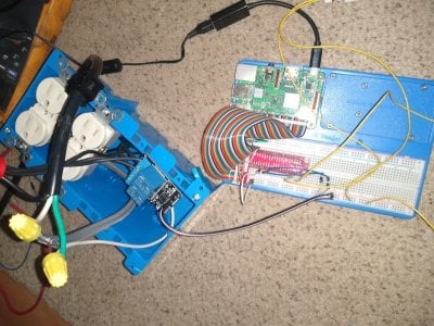
ok so after several months i finally got around to doing a small reefpi setup just for ato only so far. I have the relay and outlets setup and wired. At this point I have basically a working single switch ato. But I have a few questions. The plan is to have this be an ato for both my 55gallon and my 20 gallon which are right next to each other. I have 5 float switches total and hope to have two in each tank and one in the rodi reservour. One will be for a backup incase the other switch gets stuck on. First question is how to get the automatic disable and alert to work under the ato tab on reef pi it doesn't seem to turn the relay off? Second question is how I should go about having the backup switch turn off the pump? Is there a way to set this up within the reef pi software or would I have to wire two switches in series. Right now I am experimenting with two switches and have this python script start at startup to assign the gpio pins as input which I know I can easily just add more pins to the variable. Thanks

import RPi.GPIO as GPIO
import time
GPIO.setmode(GPIO.BCM)
chan_list = [19, 26]
GPIO.setup(chan_list, GPIO.IN, pull_up_down=GPIO.PUD_UP)

IMG_20191231_144618853.jpg
 
Last edited:
OP
OP
Ranjib

Ranjib

7500 Club Member
View Badges
Joined
Apr 16, 2016
Messages
9,848
Reaction score
17,081
Location
Pleasant Hill, Concord
Rating - 0%
0   0   0
Additionaly the ability to ad tabs will be welcome. Maybe in the setting tab that you can choose what kind of tab you like to ad.
The capabilities section under settings tab does this. Each capability is exposed as one individual tab. Capabilities (Tabs ) in reef-pi represent modularity.
 
OP
OP
Ranjib

Ranjib

7500 Club Member
View Badges
Joined
Apr 16, 2016
Messages
9,848
Reaction score
17,081
Location
Pleasant Hill, Concord
Rating - 0%
0   0   0
ok so after several months i finally got around to doing a small reefpi setup just for ato only so far. I have the relay and outlets setup and wired. At this point I have basically a working single switch ato. But I have a few questions. The plan is to have this be an ato for both my 55gallon and my 20 gallon which are right next to each other. I have 5 float switches total and hope to have two in each tank and one in the rodi reservour. One will be for a backup incase the other switch gets stuck on. First question is how to get the automatic disable and alert to work under the ato tab on reef pi it doesn't seem to turn the relay off? Second question is how I should go about having the backup switch turn off the pump? Is there a way to set this up within the reef pi software or would I have to wire two switches in series. Right now I am experimenting with two switches and have this python script start at startup to assign the gpio pins as input which I know I can easily just add more pins to the variable. Thanks

import RPi.GPIO as GPIO
import time
GPIO.setmode(GPIO.BCM)
chan_list = [19, 26]
GPIO.setup(chan_list, GPIO.IN, pull_up_down=GPIO.PUD_UP)

IMG_20191231_144618853.jpg
in reef-pi, the ato should always turn off corresponding pump before being disabled. You can use the first sensor to control the ato pump (equipment target) and the second sensor to control a macro (target macro) thats in turn disable the first ATO. Macros are versatile and can do more. Theres a disable on alert checkbox under individual ato setup that can be used to specify a total pump time run, beyond which reef-pi will disable the ato, if used. Its hourly, and will only work at hourly limits and when auto-disabled you have to either wait for the next hour or recreate the ato to re-enable it immediately.
 

Phildago

Well-Known Member
View Badges
Joined
Oct 11, 2019
Messages
854
Reaction score
933
Location
Broad Channel
Rating - 0%
0   0   0
I just hit my first major road block. I did some wiring today, plugged my pi 3 into the outlet and tried to login and got nothing. I tried shh, nothing. I tried plugging into the ethernet, still nothing.

That's when I logged onto my router to look for the ip, and it said the raspberry pi wasn't connected to the internet.

What could've gone wrong? What are my next steps in troubleshooting this?
 

thoeffe

Community Member
View Badges
Joined
Oct 6, 2018
Messages
80
Reaction score
26
Rating - 0%
0   0   0
in reef-pi, the ato should always turn off corresponding pump before being disabled. You can use the first sensor to control the ato pump (equipment target) and the second sensor to control a macro (target macro) thats in turn disable the first ATO. Macros are versatile and can do more. Theres a disable on alert checkbox under individual ato setup that can be used to specify a total pump time run, beyond which reef-pi will disable the ato, if used. Its hourly, and will only work at hourly limits and when auto-disabled you have to either wait for the next hour or recreate the ato to re-enable it immediately.

As for using macro I tried but couldn't find where I could tell it to detect the state of the secondary float to control the macro
Ok so if I am understanding you correctly, when I set frequency to 10 seconds, enable alerts, enable the disable on alert after 30 seconds, It is normal for it to shut off the relay after 30 seconds when I first enter in the settings for a new ato and to disable the ato status for an hour. If i reenable it under the existing ato and save the settings it is supposed to immediately shut off as the relay turns back on because an hour has not passed yet?.
 
Last edited:
OP
OP
Ranjib

Ranjib

7500 Club Member
View Badges
Joined
Apr 16, 2016
Messages
9,848
Reaction score
17,081
Location
Pleasant Hill, Concord
Rating - 0%
0   0   0
I just hit my first major road block. I did some wiring today, plugged my pi 3 into the outlet and tried to login and got nothing. I tried shh, nothing. I tried plugging into the ethernet, still nothing.

That's when I logged onto my router to look for the ip, and it said the raspberry pi wasn't connected to the internet.

What could've gone wrong? What are my next steps in troubleshooting this?
Do you have a build thread? If raspberry pi is going out of network then its something to do with network setup or router/gateway being flaky, something beyond reef-pi. But this can definitely be addressed. When I used to run reef-pi controllers in my Comcast /xfinity home network it used to be a common problem, so much so I deployed a nightly cron job to just restart wifi network on every pi. For the last one year, I have google wifi network that segregates the IoT devices in their own network, and that has fixed it.
There are many otherways to workaround this problem (like deploying some hourly script that checks for network and then restart it when needed), you can try those, as well as finding out whats happening exactly and solve it at the root
 
OP
OP
Ranjib

Ranjib

7500 Club Member
View Badges
Joined
Apr 16, 2016
Messages
9,848
Reaction score
17,081
Location
Pleasant Hill, Concord
Rating - 0%
0   0   0
Ok so if I am understanding you correctly, when I set frequency to 10 seconds, enable alerts, enable the disable on alert after 30 seconds, It is normal for it to shut off the relay after 30 seconds when I first enter in the settings for a new ato and to disable the ato status for an hour. If i reenable it under the existing ato and save the settings it is supposed to immediately shut off as the relay turns back on because an hour has not passed yet?.
yes thats precisely what i meant. For double safety, test it out with your build
 
Back
Top