reef-pi :: An opensource reef tank controller based on Raspberry Pi.

Bzar

Community Member
View Badges
Joined
Apr 11, 2019
Messages
32
Reaction score
66
Rating - 0%
0   0   0
Just talked with local electronics parts store guy. He has some of these he was playing with. He said they work, but hasn't tried the pwm or obviously never with reef'pi. I'm going to go grab a couple to test out...will report back how well they work.
 

janos

Active Member
View Badges
Joined
Jun 4, 2017
Messages
267
Reaction score
259
Location
Toronto,Canada
Rating - 0%
0   0   0
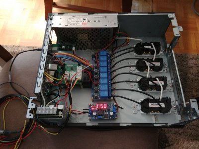
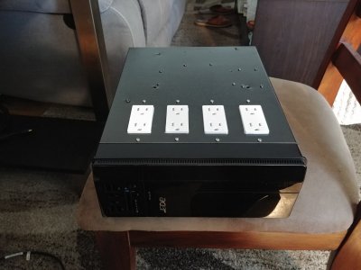
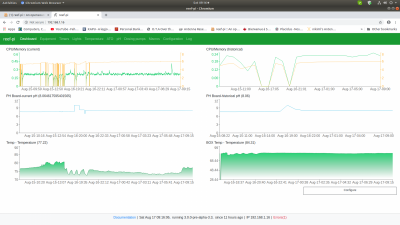
Hi to all,just need to tell thank you to Ranjib for that wonderful Reef-pi and Michael Lane for the V2 board,what makes my life 100 times easier.Some pics from my box.

20190816_181335_HDR.jpg 20190816_182747_HDR.jpg Screenshot from 2019-08-17 09-16-12.png
 

crusso1993

7500 Club Member
View Badges
Joined
Oct 21, 2018
Messages
8,671
Reaction score
44,651
Location
SW, FL, USA
Rating - 0%
0   0   0
Hi to all,just need to tell thank you to Ranjib for that wonderful Reef-pi and Michael Lane for the V2 board,what makes my life 100 times easier.Some pics from my box.

20190816_181335_HDR.jpg 20190816_182747_HDR.jpg Screenshot from 2019-08-17 09-16-12.png

Sleek, clean and beautifully done!
 

janos

Active Member
View Badges
Joined
Jun 4, 2017
Messages
267
Reaction score
259
Location
Toronto,Canada
Rating - 0%
0   0   0
Thank you crusso1993,that is my second box the first one was just basic running 2 year long without a hick up now i got a beautiful hat from Michael Lane and that is my second build.Happy with the outcome. PH was big part of the second build.
 

crusso1993

7500 Club Member
View Badges
Joined
Oct 21, 2018
Messages
8,671
Reaction score
44,651
Location
SW, FL, USA
Rating - 0%
0   0   0
Thank you crusso1993,that is my second box the first one was just basic running 2 year long without a hick up now i got a beautiful hat from Michael Lane and that is my second build.Happy with the outcome. PH was big part of the second build.

Very cool!
I originally joined R2R for a number of reasons. One of the biggest reasons was because I wanted to build a control system for a big tank I was going to be starting. I got pretty involved on this thread and a number of other people's build threads. Long story = short story = life happened and my plans were majorly changed. I never built the big tank or controller. I still have the old Antec computer case, various parts bought and things waiting. Since that time, I've always followed and been mildly involved in this thread. The improvements made by @Ranjib and others, just since the end of last year, have been outstanding. I'm unsure when I'll actually be able to start moving forward with everything because, well, life throws curve balls and sliders sometimes but I always enjoy others sharing their reef pi builds! Thanks for sharing yours and sorry about the short novel here!
 
Last edited:
OP
OP
Ranjib

Ranjib

7500 Club Member
View Badges
Joined
Apr 16, 2016
Messages
9,848
Reaction score
17,081
Location
Pleasant Hill, Concord
Rating - 0%
0   0   0
Hi to all,just need to tell thank you to Ranjib for that wonderful Reef-pi and Michael Lane for the V2 board,what makes my life 100 times easier.Some pics from my box.

20190816_181335_HDR.jpg 20190816_182747_HDR.jpg Screenshot from 2019-08-17 09-16-12.png
Awesome :) . Congrats on finishing the build and thank you for the kind words, what a great way to start my day :)
 

Bzar

Community Member
View Badges
Joined
Apr 11, 2019
Messages
32
Reaction score
66
Rating - 0%
0   0   0
well....tried to get the 700ma version of driver working. It's driving a string of 10 3w LED's just fine, but for some reason I can't get the PWM to work. It's either always on or always off depending on the wiring configuration, not sure what's going on. I've tried all worts of wiring combinations, and all sorts of reef-pi settings. Will have to test more later. Anyone have any idea's why this may be the case?
http://www.xlsemi.com/datasheet/XL4001 datasheet.pdf

Is there a way to test if the PCA9685 PWM is working properly?
 

bala murugan 00500

Community Member
View Badges
Joined
Oct 16, 2018
Messages
34
Reaction score
90
Location
coimbatore ,India
Rating - 0%
0   0   0
Good news, thanks. Any idea how I'd hook up the pwm and reef-pi setting for one of these?
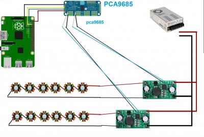
it is simple .. here I'm drawn one simple drawing
12356.jpg


in reef pi first, u have to enable the PCA9685 option.
Screenshot (176).png

after that, you have to add pin number (pin you connecter in PCA9685) in configuration > connection > Jacks.
after that reload the reef pi .

Screenshot (178).png


then under the light option, you have to create by clicking +. ... then u can assign separate led control over there

Screenshot (179).png


I'm not an experienced person in feer pi and in electric .. just sharing what I know and what I tried and work
if I'm wrong, please correct me
 
Last edited:

Bzar

Community Member
View Badges
Joined
Apr 11, 2019
Messages
32
Reaction score
66
Rating - 0%
0   0   0
it is simple .. here I'm drawn one simple drawing
12356.jpg


in reef pi first, u have to enable the PCA9685 option.
Screenshot (176).png

after that, you have to add pin number (pin you connecter in PCA9685) in configuration > connection > Jacks.
after that reload the reef pi .

Screenshot (178).png


then under the light option, you have to create by clicking +. ... then u can assign separate led control over there

Screenshot (179).png


I'm not an experienced person in feer pi and in electric .. just sharing what I know and what I tried and work
if I'm wrong, please correct me
Awesom thanks for detailed reply. Yeah looks pretty much what I tried. only difference is my setup has the pi 3.3 going to the vcc not the v+ of the PCA9685....maybe I'll try that. Maybe another PCA9685 and another driver.....perhaps mines broken. I also might have to find my old oscilloscope to see if the pwm is working.

At a loss atm :/
 

bala murugan 00500

Community Member
View Badges
Joined
Oct 16, 2018
Messages
34
Reaction score
90
Location
coimbatore ,India
Rating - 0%
0   0   0
Awesom thanks for detailed reply. Yeah looks pretty much what I tried. only difference is my setup has the pi 3.3 going to the vcc not the v+ of the PCA9685....maybe I'll try that. Maybe another PCA9685 and another driver.....perhaps mines broken. I also might have to find my old oscilloscope to see if the pwm is working.

At a loss atm :/
i'm really sorry ... u have to connect to VCC only .. i make a mistake by connecting in V+

12356.jpg
 

Bzar

Community Member
View Badges
Joined
Apr 11, 2019
Messages
32
Reaction score
66
Rating - 0%
0   0   0
i'm really sorry ... u have to connect to VCC only .. i make a mistake by connecting in V+

12356.jpg
So I've got it connected as shown, and now I'm at a loss. In a nutshell it seems the reef-pi isn't producing a pwm signal. The driver is working, and the PWM input on the driver does turn the LED's off when a 3v current is applied. Tried multiple PCA9685's and it doesn't change the situation. Put an oscilloscope and multimeter on the PWM signal wires from the PCA9685 and there's no current. Not sure where the breakdown is, but it's looking like something I've missed in the setup to make the Reef-Pi/PCA9685 work? smh
 
OP
OP
Ranjib

Ranjib

7500 Club Member
View Badges
Joined
Apr 16, 2016
Messages
9,848
Reaction score
17,081
Location
Pleasant Hill, Concord
Rating - 0%
0   0   0
So I've got it connected as shown, and now I'm at a loss. In a nutshell it seems the reef-pi isn't producing a pwm signal. The driver is working, and the PWM input on the driver does turn the LED's off when a 3v current is applied. Tried multiple PCA9685's and it doesn't change the situation. Put an oscilloscope and multimeter on the PWM signal wires from the PCA9685 and there's no current. Not sure where the breakdown is, but it's looking like something I've missed in the setup to make the Reef-Pi/PCA9685 work? smh
Do you have a build thread where we can track you circuit/build and troubleshoot systematically.
Lets start with checking voltage at the pca9685 pin and then track it from there to led input, for a single channel
 

Bzar

Community Member
View Badges
Joined
Apr 11, 2019
Messages
32
Reaction score
66
Rating - 0%
0   0   0
Do you have a build thread where we can track you circuit/build and troubleshoot systematically.
Lets start with checking voltage at the pca9685 pin and then track it from there to led input, for a single channel

Well after stepping away for a while I was thinking to myself.....hmmmmm it's got to be the pin on the Raspberry Pi. So I changed to my backup Pi. I installed the image I was using on the original Pi, tried again, and failed the same way. So now I'm sure it's a setting. So I jump into the terminal and run a check...

sudo i2cdetect -y 1
Error!

It's supposed to look something like this....
0 1 2 3 4 5 6 7 8 9 a b c d e f
00: -- -- -- -- -- -- -- -- -- -- -- -- --
10: -- -- -- -- -- -- -- -- -- -- -- -- -- -- -- --
20: -- -- -- -- -- -- -- -- -- -- -- -- -- -- -- --
30: -- -- -- -- -- -- -- -- -- -- -- -- -- -- -- --
40: 40 -- -- -- -- -- -- -- -- -- -- -- -- -- -- --
50: -- -- -- -- -- -- -- -- -- -- -- -- -- -- -- --
60: -- -- -- -- -- -- -- -- -- -- -- -- -- -- -- --
70: 70 -- -- -- -- -- -- --


So
sudo raspi-config > Interface Options > i2c > Turn on > then reboot......and WORKS!
What a bone head mistake...I should have checked that setting to start with and I wouldn't have had to change the Pi's, oh well...everyone can learn from my mistake :) I could have sworn I turned it on, but I guess not. Works now, YAY!
 
OP
OP
Ranjib

Ranjib

7500 Club Member
View Badges
Joined
Apr 16, 2016
Messages
9,848
Reaction score
17,081
Location
Pleasant Hill, Concord
Rating - 0%
0   0   0
Well after stepping away for a while I was thinking to myself.....hmmmmm it's got to be the pin on the Raspberry Pi. So I changed to my backup Pi. I installed the image I was using on the original Pi, tried again, and failed the same way. So now I'm sure it's a setting. So I jump into the terminal and run a check...

sudo i2cdetect -y 1
Error!

It's supposed to look something like this....
0 1 2 3 4 5 6 7 8 9 a b c d e f
00: -- -- -- -- -- -- -- -- -- -- -- -- --
10: -- -- -- -- -- -- -- -- -- -- -- -- -- -- -- --
20: -- -- -- -- -- -- -- -- -- -- -- -- -- -- -- --
30: -- -- -- -- -- -- -- -- -- -- -- -- -- -- -- --
40: 40 -- -- -- -- -- -- -- -- -- -- -- -- -- -- --
50: -- -- -- -- -- -- -- -- -- -- -- -- -- -- -- --
60: -- -- -- -- -- -- -- -- -- -- -- -- -- -- -- --
70: 70 -- -- -- -- -- -- --


So
sudo raspi-config > Interface Options > i2c > Turn on > then reboot......and WORKS!
What a bone head mistake...I should have checked that setting to start with and I wouldn't have had to change the Pi's, oh well...everyone can learn from my mistake :) I could have sworn I turned it on, but I guess not. Works now, YAY!
Yay :)
 

Bzar

Community Member
View Badges
Joined
Apr 11, 2019
Messages
32
Reaction score
66
Rating - 0%
0   0   0
Also forgot to mention....depending on the version of OS on the Raspberry Pi if someone is looking to run the "sudo i2cdetect -y 1" (or "sudo i2cdetect -y 0" for original Pi's) they may not have the tools pre-installed to run the command. To get the i2c tools in the Raspberry Pi just type...
sudo apt-get install i2c-tools

Now to finish building 300 watts of LED's fixture over 10 channels (parts all in were like $170 CDN :); then on to stepper controlled dosing pumps and pH. I'll put up a build thread soon.
 

bala murugan 00500

Community Member
View Badges
Joined
Oct 16, 2018
Messages
34
Reaction score
90
Location
coimbatore ,India
Rating - 0%
0   0   0
Well after stepping away for a while I was thinking to myself.....hmmmmm it's got to be the pin on the Raspberry Pi. So I changed to my backup Pi. I installed the image I was using on the original Pi, tried again, and failed the same way. So now I'm sure it's a setting. So I jump into the terminal and run a check...

sudo i2cdetect -y 1
Error!

It's supposed to look something like this....
0 1 2 3 4 5 6 7 8 9 a b c d e f
00: -- -- -- -- -- -- -- -- -- -- -- -- --
10: -- -- -- -- -- -- -- -- -- -- -- -- -- -- -- --
20: -- -- -- -- -- -- -- -- -- -- -- -- -- -- -- --
30: -- -- -- -- -- -- -- -- -- -- -- -- -- -- -- --
40: 40 -- -- -- -- -- -- -- -- -- -- -- -- -- -- --
50: -- -- -- -- -- -- -- -- -- -- -- -- -- -- -- --
60: -- -- -- -- -- -- -- -- -- -- -- -- -- -- -- --
70: 70 -- -- -- -- -- -- --


So
sudo raspi-config > Interface Options > i2c > Turn on > then reboot......and WORKS!
What a bone head mistake...I should have checked that setting to start with and I wouldn't have had to change the Pi's, oh well...everyone can learn from my mistake :) I could have sworn I turned it on, but I guess not. Works now, YAY!
Update your light build, when u got finished
 
Back
Top