Thank you for this. My one concern is that I am already using pin 12 for the power control circuit?
You should be able to use pin 18 for pwm instead. Or you just use another pin for the power control, you have more options there to choose from.
Follow along with the video below to see how to install our site as a web app on your home screen.
Note: This feature may not be available in some browsers.
Thank you for this. My one concern is that I am already using pin 12 for the power control circuit?


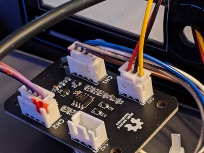
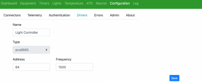
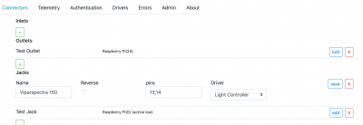
Yes. Pwm outputs on mike lane’s hat are controlled with 9685 driver.So I am trying to get my viparspectra hooked up to my reefpi, I have the @Michael Lane goby hat and adapter, I am trying to make sure I wire it correctly, from the picture on the upper right jst connector is the yellow Chanel 2 the black(center) the ground and the red Chanel 1? After I get the wiring correct do I need to setup a pca9685 driver for it and then add a new jack calling pins 13,14 and listing the driver I created?


can you confirm if I have correctly labeled the pins that go out of the viparspectra adapter to the hat, specifically that the ground is the center pin on the adapter?Yes. Pwm outputs on mike lane’s hat are controlled with 9685 driver.
then final step is to setup the light on light tab with the jack you created.
i can’t say for sure but the Mars adapter looks very similar and there is diagram showing ground in the middle. Maybe send a dm to Mike lane. He has been very helpful to me before when I’ve asked questions.can you confirm if I have correctly labeled the pins that go out of the viparspectra adapter to the hat, specifically that the ground is the center pin on the adapter?
If i understand it correctly i realy need t oreverse everything! so On = OFF to?Here's my original post

reef-pi :: An opensource reef tank controller based on Raspberry Pi.
Ok I understand, how do you assign pin number to pi, so pin 8 cant be same as pin 8 on hat..?www.reef2reef.com
That looks to me like it will work.If i understand it correctly i realy need t oreverse everything! so On = OFF to?
So what i want:

What i need to write if i run it with a timer:

i wil! i wil not activate it yet as i am not at home and do not want my terrarium to flood ... XDThat looks to me like it will work.
Please let us know how it goes.
We can tinker with it and salvage what's usable. It will be really cool if we can get reef-pi running in one of those. I dont know how many custom components it has, and how easy it will be to get those working with reef-pi. If its a lot of work, its probably not worth , since theres only a handful of these units present. But without testing out, its hard to say how much effort involved
Nope :-(have you had the chance to look into this? i also have a bricked vertex cerebra id love to run reef-pi on
:-( . this is super easy with api/coding , but alas nothing fancy with the UI.@Ranjib is there an easy methode to just set 1 Light output and just copy this to my other light's ? I have quite some for the Terrarium.(also still hoping on random lightning/rain thing or triger system with real time information. )

@Ranjib I can't get the lights to power, is there a step I am missing? Other than running power to my pi do I need to hook up an additional power source to my goby hat to get it to work?So I am trying to get my viparspectra hooked up to my reefpi, I have the @Michael Lane goby hat and adapter, I am trying to make sure I wire it correctly, from the picture on the upper right jst connector is the yellow Chanel 2 the black(center) the ground and the red Chanel 1? After I get the wiring correct do I need to setup a pca9685 driver for it and then add a new jack calling pins 13,14 and listing the driver I created?


I don’t have this setup or tinkered with in past . I’m sorry I can’t validate the circuit, let’s wait for someone with this unit to respond@Ranjib I can't get the lights to power, is there a step I am missing? Other than running power to my pi do I need to hook up an additional power source to my goby hat to get it to work?
I used wire normally closed, because of heater. I didn’t want it to turn off when it’s not being controlled. I can see reasons for the opposite as well. If you are doing scratch build, then no reason to have mixed setup as well, if that suits your need,Question. Do you guys wire your relays normally open or normally closed? Which and why?
If I unplug what I think is the ground wire the light will turn on but I can't control it, it is either on or off. If I plug the ground wire in then the lights turn off immediately. Anyone else experience this?@Ranjib I can't get the lights to power, is there a step I am missing? Other than running power to my pi do I need to hook up an additional power source to my goby hat to get it to work?
Question. Do you guys wire your relays normally open or normally closed? Which and why?
thank you for this post, the step by step you provided really helpful. finally, I can use my pH probe. I admit that this cheap pH probe perhaps lacks of accuracy if compared to ezo pH probe. But in my place, the ezo is really expensive and I can not afford it.Adding analog sensors with ADS1115
Michael Lane has been working on a new ADS1015/ADS1115 driver for reef-pi.
This brings new possibilities to Reef-Pi:
Any analog sensor can be used as long as the analog signal is in between 2.0V to 5.5V.
- PH/Orp probes
- Pressure sensors
- Flow sensors
- Etc.
ADS1115 16-Bit ADC - 4 Channel with Programmable Gain Amplifier

ADS1115 Features:
I had an ADS1115 board so I tried if my PH probe is working. So I made a “How to guide” maybe it will be of use for others. I used a Raspberry Pi 2 Model B with Reef-Pi version 3.5.
- Resolution: 16 Bits
- Programmable Sample Rate: 8 to 860 Samples/Second
- Power Supply/Logic Levels: 2.0V to 5.5V
- Low Current Consumption: Continuous Mode: Only 150µA Single-Shot Mode: Auto Shut-Down
- Internal Low-Drift Voltage Reference
- Internal Oscillator
- Internal PGA: up to x16
- I2C Interface: 4-Pin-Selectable Addresses
- Four Single-Ended or 2 Differential Inputs
- Programmable Comparator
Add driver under Configuration/Drivers

Configure the Driver:

Name: PH
Type: ads1115
Address: standard is 72
Gain: 2/3, 1, 2, 4, 8 or 16
An Adafruit tutorial has this guidance.
# Choose a gain of 1 for reading voltages from 0 to 4.09V.
# Or pick a different gain to change the range of voltages that are read:
# - 2/3 = +/-6.144V (High Gain, Sensitive to noise)
# - 1 = +/-4.096V
# - 2 = +/-2.048V
# - 4 = +/-1.024V
# - 8 = +/-0.512V
# - 16 = +/-0.256V (Low Gain, Not Sensitive to Noise)
# See table 3 in the ADS1015/ADS1115 datasheet for more info on gain.
Reboot (Configuration/Admin)
Add analog input under Configuration/Connectors

Configure the connector

Name: PHpin0
Pins: 0 (depends what pin you use on the ADS1115 board)
Driver: PH
Reload (Configuration/Admin)
Add the probe under pH

Configure the PH probe

Name: PH
Analog input: PHpin0
Check frequency: 10
Ph status: Enabled
The other settings are not mandatory.
Calibration
The first readings will be high:

Therefore you need to calibrate!
To be able to calibrate you first have to disable the Ph status
Enjoy!
- Edit ph.
- Disable probe.
- Save
- Calibrate
- Rinse probe in rodi
- Place in 7 calibration fluid
- Wait for readings to stabilize
- Set cal value to 7 (Midpoint)
- Push Run
- Rinse probe
- Put in 10 calibration fluid
- Set cal value to 10 (Second Point)
- Run
- Enable probe
- Rinse probe and check both 7 and 10 and make sure it’s close.

