reef-pi :: An opensource reef tank controller based on Raspberry Pi.

LongBeachReefer562

Community Member
View Badges
Joined
May 19, 2019
Messages
46
Reaction score
26
Rating - 0%
0   0   0
Those controllers usually don't change the line frequency so its not going to work (they just chop some part of the waveform like a normal triac dimmer).

Have you triple checked the tubing? Also, mark the rollers with a sharpy and count actual revolutions per minute to see if the motor is running faster. Sync motors would only run at line speed or some multiple of it - so a multiple of 60Hz. Its possible whatever BRS is getting has different gearing mounted in it of course, or they're loading different ID tubing.
The motors are rated 50hz-60hz which is kinda why I figured I had some chance of slightly varying the speed but I see what youre saying about chopping the waveform.

Yeah I've replaced all tubing recently as well as the internal tubing, all is in working order and there's no airbubbles or anything.

The doser are a couple years apart in age so perhaps theyre geared differently over the years like you had mentioned.

I'm not curious enough to tear apart either of my dosers though at $80 a pop...just going to have to live with it lol.

Thanks for your feedback!!!
 

Mikeneedsahobby

Well-Known Member
View Badges
Joined
Sep 16, 2018
Messages
516
Reaction score
922
Rating - 0%
0   0   0
Hi just a quick question, now I have done pwm on light and exchanged some leds with 420nm and 400nm, all whats is left for full auto is missing sensors when liquids are running low. I use 7 dosing pumps for dosing . No wc for allmost 3 years. Can this be done on pwm? If so with what. I have 2 expansion boards I can use. Other stuff is all automated on reefpi ok milwakee controller for ca reactor is not on pi..tnx

8DF4C774-68B6-425E-9D0F-477C0278C19C.jpeg
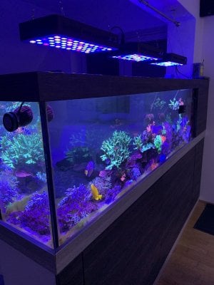
Nice tank!

what sensors are looking to use? Float sensors typically run to gpio.
 
OP
OP
Ranjib

Ranjib

7500 Club Member
View Badges
Joined
Apr 16, 2016
Messages
9,848
Reaction score
17,081
Location
Pleasant Hill, Concord
Rating - 0%
0   0   0
Hello guys,
Using reef-pi for more than year now. I've got a strange problem which I suspect might be hardware one.
Sometimes when controller switch off/on devices (via timer) all the temp sensors (3 pcs) start reporting 0 deg C temperature. If I don't switch any equipment on/off all is fine.

I've also noticed that after this foult my external temp sensor is getting hot. When I reboot device all is fine but sensor is reporting 50 deg C or something close to that and decreasing to my room temp.

Any idea what can couse this behaviour? I suspect that there must be circut short somewhere. I'd replace the sensor straight away but as I said this problem only occurs while switching on and off other equimpent - also which sensor? All 3? This suggest that the problem is somewhere else, not the sensor itself. On the other hand all of them are conected to the same data cable so maybe this data pin is somehow shorting? They don't fail after every single switch. It can work ok for lets say 10 switches and then fail on 11th. Reverse voltage coming back from switch and somehow interupt proper work of sensors?
Definitely something related to electrical interference. Is your pi showing under voltage during that time ? I would test with alternate probe to first isolate if it’s probe related or any of the equipment . Do you have a grounding probe in tank ?
 

pies666

New Member
View Badges
Joined
Nov 25, 2019
Messages
12
Reaction score
9
Rating - 0%
0   0   0
Definitely something related to electrical interference. Is your pi showing under voltage during that time ? I would test with alternate probe to first isolate if it’s probe related or any of the equipment . Do you have a grounding probe in tank ?
Hey,
My Pi is working fine all the time. I disconected temp sensors one by one - problem persist. It only occures while reef-pi is switching on or off protein skimmer (only this device). I do not have grounding probe in tank. I will check out if changing the power socket for protein skimmer will help. Maybe it's a problem with one relay.
 

Matevz Savarin

Active Member
View Badges
Joined
Dec 5, 2018
Messages
209
Reaction score
163
Rating - 0%
0   0   0
Nice tank!

what sensors are looking to use? Float sensors typically run to gpio.
Thanks, runong out of coral space,
I am Looking for pwm water level sensors, but I dont know if they are compatible with pi..
Float I use only one for ato and one directly on pump without pi. Its bulletproof. So if the one on reefpi fails second turns off power of ato pump.
 

belly.89

New Member
View Badges
Joined
Jul 12, 2020
Messages
2
Reaction score
1
Location
Netherlands
Rating - 0%
0   0   0
Adding analog sensors with ADS1115

Michael Lane has been working on a new ADS1015/ADS1115 driver for reef-pi.

This brings new possibilities to Reef-Pi:
  • PH/Orp probes
  • Pressure sensors
  • Flow sensors
  • Etc.
Any analog sensor can be used as long as the analog signal is in between 2.0V to 5.5V.

ADS1115 16-Bit ADC - 4 Channel with Programmable Gain Amplifier

ADS1115.png


ADS1115 Features:
  • Resolution: 16 Bits
  • Programmable Sample Rate: 8 to 860 Samples/Second
  • Power Supply/Logic Levels: 2.0V to 5.5V
  • Low Current Consumption: Continuous Mode: Only 150µA Single-Shot Mode: Auto Shut-Down
  • Internal Low-Drift Voltage Reference
  • Internal Oscillator
  • Internal PGA: up to x16
  • I2C Interface: 4-Pin-Selectable Addresses
  • Four Single-Ended or 2 Differential Inputs
  • Programmable Comparator
I had an ADS1115 board so I tried if my PH probe is working. So I made a “How to guide” maybe it will be of use for others. I used a Raspberry Pi 2 Model B with Reef-Pi version 3.5.

Add driver under Configuration/Drivers
1.png


Configure the Driver:
2.png

Name: PH
Type: ads1115
Address: standard is 72
Gain: 2/3, 1, 2, 4, 8 or 16

An Adafruit tutorial has this guidance.
# Choose a gain of 1 for reading voltages from 0 to 4.09V.
# Or pick a different gain to change the range of voltages that are read:
# - 2/3 = +/-6.144V (High Gain, Sensitive to noise)
# - 1 = +/-4.096V
# - 2 = +/-2.048V
# - 4 = +/-1.024V
# - 8 = +/-0.512V
# - 16 = +/-0.256V (Low Gain, Not Sensitive to Noise)
# See table 3 in the ADS1015/ADS1115 datasheet for more info on gain.

Reboot (Configuration/Admin)

Add analog input under Configuration/Connectors
3.png


Configure the connector
4.png

Name: PHpin0
Pins: 0 (depends what pin you use on the ADS1115 board)
Driver: PH
Reload (Configuration/Admin)

Add the probe under pH
5.png


Configure the PH probe
6.png

Name: PH
Analog input: PHpin0
Check frequency: 10
Ph status: Enabled
The other settings are not mandatory.

Calibration
The first readings will be high:
7.png

Therefore you need to calibrate!

To be able to calibrate you first have to disable the Ph status
  • Edit ph.
  • Disable probe.
  • Save
  • Calibrate
  • Rinse probe in rodi
  • Place in 7 calibration fluid
  • Wait for readings to stabilize
  • Set cal value to 7 (Midpoint)
  • Push Run
  • Rinse probe
  • Put in 10 calibration fluid
  • Set cal value to 10 (Second Point)
  • Run
  • Enable probe
  • Rinse probe and check both 7 and 10 and make sure it’s close.
Enjoy!

Thank you for this tutorial. I tried to add a PH sensor to my RPI4 with reef-pi version 3.5. All the steps are clear but I run into a problem, maybe you know the solution?


When I connect the PH probe and card (PH-4502C) to the RPI4, the RPI4 won't boot. When I disconnect the 5v to the PH-4502C, the RPi4 boots normally. When I plug the 5v from the RPI4 to the PH-4502C when the RPI4 runs, the system runs normally but doesn't find any signal from the PH probe...

Hopefully my problem is clear and someone knows what is going wrong?

Thanks in advance.
 

Kurtzisa

Community Member
View Badges
Joined
Mar 21, 2020
Messages
79
Reaction score
70
Location
Parma, Italy
Rating - 0%
0   0   0
@Ranjib I think there is a bug in PH configuration tab. I use three ph-board by Roberto Buti
I tested it with these parameters
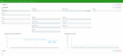
I check my PH every 5 seconds, the PH in my reactor is 6.62. My PH control the CO2 solenoid valve. My upper threshold is 8, my lower threshold is 7. I cannot set the hysteresis, every time I wrote something the value is always 0 or I see a red error "hysteresis_less_than" and nothing else.
when I save the configuration, my solenoid valve turns on and off every 5 seconds.

I tested with reef-pi 3.5 and reef-pi 3.2, I checked the connection, I rebuild my wire.

any suggestion?

PH error.png
 

BenB

Active Member
View Badges
Joined
Jun 11, 2019
Messages
112
Reaction score
155
Rating - 0%
0   0   0
Thank you for this tutorial. I tried to add a PH sensor to my RPI4 with reef-pi version 3.5. All the steps are clear but I run into a problem, maybe you know the solution?


When I connect the PH probe and card (PH-4502C) to the RPI4, the RPI4 won't boot. When I disconnect the 5v to the PH-4502C, the RPi4 boots normally. When I plug the 5v from the RPI4 to the PH-4502C when the RPI4 runs, the system runs normally but doesn't find any signal from the PH probe...

Hopefully my problem is clear and someone knows what is going wrong?

Thanks in advance.

When I worked on this,
The ads1115 was connected to the 3.3 v and ground of the pi, the phboard was connected to th 5v and to the ground of the pi. The signal out of the phboard connected to pin0 of the ads1115. And the ads1115 needs to be connected to the pi with sda and scl.

I hope this helps.
 

belly.89

New Member
View Badges
Joined
Jul 12, 2020
Messages
2
Reaction score
1
Location
Netherlands
Rating - 0%
0   0   0
When I worked on this,
The ads1115 was connected to the 3.3 v and ground of the pi, the phboard was connected to th 5v and to the ground of the pi. The signal out of the phboard connected to pin0 of the ads1115. And the ads1115 needs to be connected to the pi with sda and scl.

I hope this helps.

Thank you for your response. That is exactly how I connected everything. That looks like I did it alright. Strang that the RPi doesn’t boot anymore.
 

Yov

Community Member
View Badges
Joined
May 24, 2020
Messages
51
Reaction score
44
Rating - 0%
0   0   0
@Ranjib I have a strange problem with the Macro's.
i made a macro :
1603697065569.png

-Spray system Wifi on
-wait 15sec
-Spray system Wifi off
-Fan4 relais on
-Fan 2 relais on
-wait 10sec
-Spray system Wifi off (second time! i wil explane/ not in picture i wil also explane)
-wait 600sec
-Fan4 relais off
-Fan 2 relais off

So , i first made this macro without the extra spray system off, This worked problem i notioced whas that sometimes i got a communication error and the spray system kept on going. So for this i made an extra "spray system off"

first problem i came up to: when the macro is reversible 'yes' wel then it takes the "off" comand as "on".
Second problem, suddenly my macro was "reversed" (not visual) but i heart my fans go "off" (on) first then wait 610sec then go off and spray then go off after 15sec...

very confusing.... So what i did, i just made another macro in exactly the same way, this time i did reversible "off" press run and yes this works perfect! but as soon as i add this to a timer.... nothing happens?
1603698440338.png


i put reversible "on" and exactly the same thing as the old macro happens, it works the outher way around and it turns my spray system "on" when i ask "off". Also it added up this time to the time i already had (reversed) from the old macro?"
1603698400330.png


timer at 8Pm + 610 sec : spray. (old wrong reversed way)
Now, Timer on at 8Pm +610 +610 (sprayers on at 8:20) ....

i cant get my head around this ?! is there something wrong with the macro's/timers? Strange that when i hit RUN everything works like normal, but with the timers it just goes south!
 

Des Westcott

Well-Known Member
View Badges
Joined
May 29, 2018
Messages
646
Reaction score
1,035
Location
Durban - South Africa
Rating - 0%
0   0   0
@Ranjib I think you maybe need to have a look at safety in the case of failure of a temp probe.

I'm having intermittent failures of one of my temp probes (3) and am waiting for new ones to be delivered. I've had a couple of instances where the faulty probe fails causing all three to go bad. If the Temperature Control has my heaters on when this happens, they stay on. In my case, the internal heater control in the heater takes over and cuts them off about 1.5deg higher, but if someone was using a dedicated heater unit without a built in thermostat, they could get into trouble.

I do get the "Temp Probe Failure" messages and "Temp out of Range" messages, but I have had it happen at night when I'm asleep and "actively ignoring emails" ;)

Maybe an option to "disable control" like the ATO? But would probably need the default state to de defined. Or just default to off in case of a failure.
 

Des Westcott

Well-Known Member
View Badges
Joined
May 29, 2018
Messages
646
Reaction score
1,035
Location
Durban - South Africa
Rating - 0%
0   0   0
@Ranjib I have a strange problem with the Macro's.
i made a macro :
1603697065569.png

-Spray system Wifi on
-wait 15sec
-Spray system Wifi off
-Fan4 relais on
-Fan 2 relais on
-wait 10sec
-Spray system Wifi off (second time! i wil explane/ not in picture i wil also explane)
-wait 600sec
-Fan4 relais off
-Fan 2 relais off

So , i first made this macro without the extra spray system off, This worked problem i notioced whas that sometimes i got a communication error and the spray system kept on going. So for this i made an extra "spray system off"

first problem i came up to: when the macro is reversible 'yes' wel then it takes the "off" comand as "on".
Second problem, suddenly my macro was "reversed" (not visual) but i heart my fans go "off" (on) first then wait 610sec then go off and spray then go off after 15sec...

very confusing.... So what i did, i just made another macro in exactly the same way, this time i did reversible "off" press run and yes this works perfect! but as soon as i add this to a timer.... nothing happens?
1603698440338.png


i put reversible "on" and exactly the same thing as the old macro happens, it works the outher way around and it turns my spray system "on" when i ask "off". Also it added up this time to the time i already had (reversed) from the old macro?"
1603698400330.png


timer at 8Pm + 610 sec : spray. (old wrong reversed way)
Now, Timer on at 8Pm +610 +610 (sprayers on at 8:20) ....

i cant get my head around this ?! is there something wrong with the macro's/timers? Strange that when i hit RUN everything works like normal, but with the timers it just goes south!

I've posted how to deal with this is detail before. There is a problem with the reversible macros and running macros from macros and timers. In short, a macro or a timer can only trigger a macro if it is reversible, and then it will only run it in reverse. My work around for this is to write my macros I want to trigger from another macro or timer in reverse - you need to reverse order and state - and then use those from your timer / macro (reversible)

Hope that makes sense. I'll try find my original post on the issue.
 

Des Westcott

Well-Known Member
View Badges
Joined
May 29, 2018
Messages
646
Reaction score
1,035
Location
Durban - South Africa
Rating - 0%
0   0   0
@Ranjib I have a strange problem with the Macro's.
i made a macro :
1603697065569.png

-Spray system Wifi on
-wait 15sec
-Spray system Wifi off
-Fan4 relais on
-Fan 2 relais on
-wait 10sec
-Spray system Wifi off (second time! i wil explane/ not in picture i wil also explane)
-wait 600sec
-Fan4 relais off
-Fan 2 relais off

So , i first made this macro without the extra spray system off, This worked problem i notioced whas that sometimes i got a communication error and the spray system kept on going. So for this i made an extra "spray system off"

first problem i came up to: when the macro is reversible 'yes' wel then it takes the "off" comand as "on".
Second problem, suddenly my macro was "reversed" (not visual) but i heart my fans go "off" (on) first then wait 610sec then go off and spray then go off after 15sec...

very confusing.... So what i did, i just made another macro in exactly the same way, this time i did reversible "off" press run and yes this works perfect! but as soon as i add this to a timer.... nothing happens?
1603698440338.png


i put reversible "on" and exactly the same thing as the old macro happens, it works the outher way around and it turns my spray system "on" when i ask "off". Also it added up this time to the time i already had (reversed) from the old macro?"
1603698400330.png


timer at 8Pm + 610 sec : spray. (old wrong reversed way)
Now, Timer on at 8Pm +610 +610 (sprayers on at 8:20) ....

i cant get my head around this ?! is there something wrong with the macro's/timers? Strange that when i hit RUN everything works like normal, but with the timers it just goes south!


Here's my original post


drm2215

New Member
View Badges
Joined
Sep 14, 2020
Messages
23
Reaction score
9
Location
Chicago
Rating - 0%
0   0   0
@Ranjib

Hello,
I am new to Reef-Pi and relatively unexperienced when it comes to Linux and Raspberry Pi. I am excited to get Reef-Pi up and running on my Nano Tank. I have made it through the power management section successfully and would like to focus on lighting control, but I have a question about the guide you made on Adafruit for lighting. I understand the construction and design intent but what I can't seem to figure out is how does the new Pi Zero interact with the original Reef-Pi setup? Is it completely separate and needs a separate IP address/web browser to control or does it interact with the base system?
 

Mikeneedsahobby

Well-Known Member
View Badges
Joined
Sep 16, 2018
Messages
516
Reaction score
922
Rating - 0%
0   0   0
@Ranjib

Hello,
I am new to Reef-Pi and relatively unexperienced when it comes to Linux and Raspberry Pi. I am excited to get Reef-Pi up and running on my Nano Tank. I have made it through the power management section successfully and would like to focus on lighting control, but I have a question about the guide you made on Adafruit for lighting. I understand the construction and design intent but what I can't seem to figure out is how does the new Pi Zero interact with the original Reef-Pi setup? Is it completely separate and needs a separate IP address/web browser to control or does it interact with the base system?
Normally you can add the new module with the existing module. Ie only one pi zero.

Check out this build. https://www.reef2reef.com/threads/reef-pi-build.482170/
 

drm2215

New Member
View Badges
Joined
Sep 14, 2020
Messages
23
Reaction score
9
Location
Chicago
Rating - 0%
0   0   0

Mikeneedsahobby

Well-Known Member
View Badges
Joined
Sep 16, 2018
Messages
516
Reaction score
922
Rating - 0%
0   0   0
Thanks for the build thread. I will read through it but the build guide explains the lighting module as a separate build with a different pi? Can you give me an idea where in your build thread you talk about the lighting build?
That isn’t my build thread. It is a build thread of a guy who built from scratch. He integrated several modules including lights I think. Think of the guides as written as stand alone but they all can be combined together with one pi.

For my builds I bought pre-made hats. This saves a ton of soldering and board layout headaches.
On my fresh water tank I used the pwm outputs on the hat to control mosfets that then send power to my lights. On my salt tank I built a 2nd box that contains the pwm circuits and other bits for lights and dosing. This is tied back to the main hat through i2c.

you can put your lighting module on the same board or a new board but this should be wired back to a single raspberry pi. Wire board 1 to board 2.

here is another build thread from scratch with lights. https://www.reef2reef.com/threads/another-reef-pi-build.506894/
His lights are now on my tank. I purchased them from him. I believe he builds the lighting circuit around page 6. Keep in mind that the way to control lights is different between the light manufacturers. My circuit for the beamswork light is different than my circuit for the ocean revive lights. And neither would work with kessil.
 

92Miata

Valuable Member
View Badges
Joined
Feb 26, 2020
Messages
1,523
Reaction score
2,490
Location
Richmond, VA
Rating - 0%
0   0   0
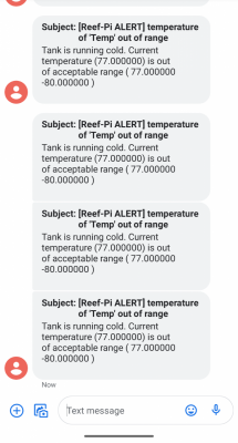
Having some temperature alerting issues - it's possible it could be some queueing going on in my email/text or one of the subsystems - but it's tough to tell with no timestamps on the actual message.

Temp.is 77.1 on the temp probe page, system is alerting that it's below 77

Screenshot_20201027-100227.png


Edit:
5 minutes later - temp probe page is now reading 77, but alerting has stopped. Strange.
 
Last edited:

Mandelstam

Well-Known Member
View Badges
Joined
Oct 29, 2017
Messages
688
Reaction score
1,119
Location
Malmö, Sweden
Rating - 0%
0   0   0
Thanks for the build thread. I will read through it but the build guide explains the lighting module as a separate build with a different pi? Can you give me an idea where in your build thread you talk about the lighting build?

No need for separate Pis for each module you can run everything from just one. The guides only show one module per pi because (my guess) it would be complicated to have guides for every possible combination. Some people have more modules running than others etc. And at the moment I don't think it's possible to connect up more than one pi to a single Reef-Pi system, ie having slave boards for different modules. I remember Ranjib talking about it though and maybe it's in the pipeline.
 

drm2215

New Member
View Badges
Joined
Sep 14, 2020
Messages
23
Reaction score
9
Location
Chicago
Rating - 0%
0   0   0
That isn’t my build thread. It is a build thread of a guy who built from scratch. He integrated several modules including lights I think. Think of the guides as written as stand alone but they all can be combined together with one pi.

For my builds I bought pre-made hats. This saves a ton of soldering and board layout headaches.
On my fresh water tank I used the pwm outputs on the hat to control mosfets that then send power to my lights. On my salt tank I built a 2nd box that contains the pwm circuits and other bits for lights and dosing. This is tied back to the main hat through i2c.

you can put your lighting module on the same board or a new board but this should be wired back to a single raspberry pi. Wire board 1 to board 2.

here is another build thread from scratch with lights. https://www.reef2reef.com/threads/another-reef-pi-build.506894/
His lights are now on my tank. I purchased them from him. I believe he builds the lighting circuit around page 6. Keep in mind that the way to control lights is different between the light manufacturers. My circuit for the beamswork light is different than my circuit for the ocean revive lights. And neither would work with kessil.
Thank you very much for your help. Do you know of a build thread using Kessil lights? Of course that is what i have.
 

HAVE YOU EVER KEPT A RARE/UNCOMMON FISH, CORAL, OR INVERT? SHOW IT OFF IN THE THREAD!

  • Yes!

    Votes: 32 45.7%
  • Not yet, but I have one that I want to buy in mind!

    Votes: 9 12.9%
  • No.

    Votes: 26 37.1%
  • Other (please explain).

    Votes: 3 4.3%

New Posts

Back
Top