reef-pi :: An opensource reef tank controller based on Raspberry Pi.

Sral

Valuable Member
View Badges
Joined
May 2, 2022
Messages
1,006
Reaction score
978
Location
Germany
Rating - 0%
0   0   0

Dave's Reef

Active Member
View Badges
Joined
Nov 4, 2018
Messages
102
Reaction score
150
Rating - 0%
0   0   0

robsworld78

Well-Known Member
View Badges
Joined
Feb 14, 2020
Messages
985
Reaction score
1,325
Location
Edmonton, Canada
Rating - 0%
0   0   0
So I've posted about Issues before with running multiple temp sensors I run 3 now because that's what I can get to work but I would like to run 6 but can never get them to work long term if I'm lucky I can get 5 to work for a few months before they start having issues. Is it possible to use one of these with reef pi?
https://www.ebay.com/itm/3339247256...tWFbdF3T8m&var=&widget_ver=artemis&media=COPY
Unfortunately that board you linked won't work, it requires an RS485 bus to connect to and special code.

Do you have any spare GPIO's on the Pi? If so you can connect a DS18B20 to different pins, like this is much better as if one goes bad it won't affect any of the others. If you're short on GPIO's you could maybe run 2 or 3 per pin.

To do this you connect them the same as GPIO 4 but you need to edit a configuration file on the Pi to enable the other pins. Here's how you do that.

Run the following command in the Pi SSH terminal window.

sudo nano /boot/config.txt

This will open a text file, scroll down to the bottom and you'll see the following line.

dtoverlay=w1-gpio

Add # in front of it to comment it out like this.

#dtoverlay=w1-gpio

Then add the following line under that for each GPIO you use, the number at the end is the GPIO number. 2nd line is using GPIO 22 as an example. You can add as many pins as you like.

dtoverlay=w1-gpio,gpiopin=4
dtoverlay=w1-gpio,gpiopin=22


After your finished press CTRL + S on keyboard to save and then CTRL + X to exit. Now power cycle the Raspberry Pi and it should work. There's nothing special to do in reef-pi, the dropdown will show all sensor ID's from all GPIO's.
 

Sral

Valuable Member
View Badges
Joined
May 2, 2022
Messages
1,006
Reaction score
978
Location
Germany
Rating - 0%
0   0   0
@davesreef that’s curious. As far as I know @Ranjib has tested with quite a lot of DS18B20 in parallel on the same pin, at least half a dozen. Although I’m not sure if he has run them long-term like you.

I would agree with @robsworld78, the amount of sensors should not be the problem itself. I would rather expect that the cables add too much capacitance and interference and that when one sensor goes bad it might start blocking communication to all sensors.
What pull-up value, supply voltage and total cable length are you using ?
Additionally you might test if one of sensors is bad, e.g. try removing them one at a time and see if you can narrow it down to one of the sensors.
The whole topology, e.g. how you connect all the lines, also has an influence since it can cause reflections.
 

elysics

Valuable Member
View Badges
Joined
Jan 15, 2020
Messages
1,591
Reaction score
1,590
Rating - 0%
0   0   0
So I've posted about Issues before with running multiple temp sensors I run 3 now because that's what I can get to work but I would like to run 6 but can never get them to work long term if I'm lucky I can get 5 to work for a few months before they start having issues. Is it possible to use one of these with reef pi?
https://www.ebay.com/itm/3339247256...tWFbdF3T8m&var=&widget_ver=artemis&media=COPY
Are you sure it's the sensor connection that's a problem and not the sensors themselves dying? If one of them breaks and they are all connected together on the same line, that can ruin communication for the rest
 

Sral

Valuable Member
View Badges
Joined
May 2, 2022
Messages
1,006
Reaction score
978
Location
Germany
Rating - 0%
0   0   0
So I've posted about Issues before with running multiple temp sensors I run 3 now because that's what I can get to work but I would like to run 6 but can never get them to work long term if I'm lucky I can get 5 to work for a few months before they start having issues. Is it possible to use one of these with reef pi?
https://www.ebay.com/itm/3339247256...tWFbdF3T8m&var=&widget_ver=artemis&media=COPY
Hmm, it’s definitely possible to make that board work, but it’s probably a bit of work to get the communication protocol right.

I do however think that either @robsworld78‘s suggestion with using 2 (or more) GPIO pins or using an ESP32 is likely the best choice here.

I could probably program the current ReefPi-ESP32 code to use one pin per sensor comparatively quick.
 

iamdan

Community Member
View Badges
Joined
Jul 1, 2022
Messages
87
Reaction score
74
Location
Western Australia
Rating - 0%
0   0   0
Hi All :)

I have a query about the reef-pi API - Specifically to do with pH readings, The below section, does that show the calibrated or non-calibrated ph reading?
1684133785506.png
 

Simonv92

Active Member
View Badges
Joined
Oct 21, 2014
Messages
145
Reaction score
105
Location
Italy
Rating - 0%
0   0   0
Hi all! I’m working on my controller; I have a Dc return pump with 0-10V input to control the speed. Everything works fine under Reef-Pi. Is there a way to create a macro that switch ON an outlet and then ramp up to the desired value the pwm outlet which control the speed? To have a slow start of the return pump… thank you!
 

elysics

Valuable Member
View Badges
Joined
Jan 15, 2020
Messages
1,591
Reaction score
1,590
Rating - 0%
0   0   0
Hi all! I’m working on my controller; I have a Dc return pump with 0-10V input to control the speed. Everything works fine under Reef-Pi. Is there a way to create a macro that switch ON an outlet and then ramp up to the desired value the pwm outlet which control the speed? To have a slow start of the return pump… thank you!
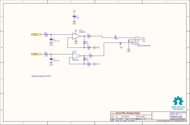
If you don't ever want fast changing pump speeds, you could just put a resistor and capacitor of fitting values on the signal line as a low pass filter. Then the signal will always ramp, in any direction.

Edit: oh if you still use pwm, probably best to also throw an opamp in to get a proper pwm to dc converter
 

Simonv92

Active Member
View Badges
Joined
Oct 21, 2014
Messages
145
Reaction score
105
Location
Italy
Rating - 0%
0   0   0
If you don't ever want fast changing pump speeds, you could just put a resistor and capacitor of fitting values on the signal line as a low pass filter. Then the signal will always ramp, in any direction.

Edit: oh if you still use pwm, probably best to also throw an opamp in to get a proper pwm to dc converter

Thank you for your reply! I already have an OP Amp circuit as shown in the image below.
I keep the PWM signal constant for every hour of the day.
My goal was to try to create a macro which does the following every time I want to restart the return pump:
- Set PWM output to 0
- Turn ON the Pump Outlet
- wait 5 sec
- increase by 10 the PWM value
- wait 5 sec
- increase by 10 the PWM value
- and so on until I reach the desired speed of the pump


Or at least, set the PWM value to reach and using a cap-resistor to slow down the ramp of the 0-10V signal
 

Attachments

  • download.png
    download.png
    89.4 KB · Views: 55

Sral

Valuable Member
View Badges
Joined
May 2, 2022
Messages
1,006
Reaction score
978
Location
Germany
Rating - 0%
0   0   0
Thank you for your reply! I already have an OP Amp circuit as shown in the image below.
I keep the PWM signal constant for every hour of the day.
My goal was to try to create a macro which does the following every time I want to restart the return pump:
- Set PWM output to 0
- Turn ON the Pump Outlet
- wait 5 sec
- increase by 10 the PWM value
- wait 5 sec
- increase by 10 the PWM value
- and so on until I reach the desired speed of the pump


Or at least, set the PWM value to reach and using a cap-resistor to slow down the ramp of the 0-10V signal
You could also use the existing resistor and capacitor. Either add 10MOhm in series to the PWM in, add another 300uF capacitor in parallel or add both a 1 M in series and a 47uF in parallel.

That way you increase your ramp duration from:
0.16M * 4.7uF = 0.75s
To:
10 M * 4.7uF = 47s
0.16 M * 300uF = 48s
1M * 47uF = 47s

So any change in the signal, e.g. from 0 to 100% or 60 to 20% will take a bit more than that time to arrive at the pump.

So you have a bit less than 100% ramp up in a bit more than 50s, or about 10% per 5s
 

Sral

Valuable Member
View Badges
Joined
May 2, 2022
Messages
1,006
Reaction score
978
Location
Germany
Rating - 0%
0   0   0
But mind what @elysics mentioned: If you build it with the additional resistor to increase the time constant:it works both ways. If you ever run into a situation where you want to shut the pump off immediately: you can't.

If you want a slow start, but a fast off you would need to build it slightly differently with a few more components (namely: 2 resistors, 2 capacitors and 1 diode per pump):
1684265900740.png


Basic functionality is this:
- the first RC (R16 and C24) smooths the PWM to a DC voltage and induces a ramp-up and down of 0,7s
- the second RC that I added will induce a slow ramp-up with something like R=10M and C=4,7µF, e.g. 47s
- the additional diode bypasses the large resistor for ramp-down only, giving you a shut-off time of about 1,4s
 

Simonv92

Active Member
View Badges
Joined
Oct 21, 2014
Messages
145
Reaction score
105
Location
Italy
Rating - 0%
0   0   0
Thank you @Sral! with this mod I can control the speed only if I'm able to turn ON or OFF the lights channel (which now I can't - even running a macro doesn't work)
My problem is the turn ON sequence. When the pump is OFF the level in the display tank decrease, when I turn it on it put water out of the tank until the return get submerged.
The fast switch OFF is not a problem since I have the power to the pump controlled by a relay (controlled by Reef-Pi)
If I'll be able to control ON/OFF of the light channel with the reistor/capacitor mod it would be perfect...
 

iamdan

Community Member
View Badges
Joined
Jul 1, 2022
Messages
87
Reaction score
74
Location
Western Australia
Rating - 0%
0   0   0
Hi All :)

I have a query about the reef-pi API - Specifically to do with pH readings, The below section, does that show the calibrated or non-calibrated ph reading?
1684133785506.png
Reason I ask is that the home assistant reef-pi add on a few versions before when it was configured to get ph readings from /api/phprobes/1/readings there was an issue with it getting and displaying the latest reading from the database but the reading of the ph from “read” api shows a different value from what’s recorded in the dashboard, so assuming that’s a uncalibrated value?
 

Sral

Valuable Member
View Badges
Joined
May 2, 2022
Messages
1,006
Reaction score
978
Location
Germany
Rating - 0%
0   0   0
Reason I ask is that the home assistant reef-pi add on a few versions before when it was configured to get ph readings from /api/phprobes/1/readings there was an issue with it getting and displaying the latest reading from the database but the reading of the ph from “read” api shows a different value from what’s recorded in the dashboard, so assuming that’s a uncalibrated value?
Sry, I sadly can’t answer your question. If nobody else can, I would recommend a „simple“ test: calibrate your pH value to something odd, for example:
If your current pH is around 8.3, calibrate your calibration points not to their nominal value, but 1.0 pH higher, if possible.

If the value that is then returned shows 9.3, you know it is the calibrated value. If it continues to show around 8.3 you know it is uncalibrated.
 

Sral

Valuable Member
View Badges
Joined
May 2, 2022
Messages
1,006
Reaction score
978
Location
Germany
Rating - 0%
0   0   0
Thank you @Sral! with this mod I can control the speed only if I'm able to turn ON or OFF the lights channel (which now I can't - even running a macro doesn't work)
My problem is the turn ON sequence. When the pump is OFF the level in the display tank decrease, when I turn it on it put water out of the tank until the return get submerged.
The fast switch OFF is not a problem since I have the power to the pump controlled by a relay (controlled by Reef-Pi)
If I'll be able to control ON/OFF of the light channel with the reistor/capacitor mod it would be perfect...
Yeah, macros are a bit weird right now.

if you want 100% pump power every time, you could try to use the PCA9685 channel (if you are using a PCA9685 for PWM ?) as an outlet. I believe that is possible.
 

Coolhack

Community Member
View Badges
Joined
Jul 21, 2019
Messages
80
Reaction score
50
Location
Anywhere
Rating - 0%
0   0   0
Hello reefers, wait, that didn't sound right. Hello all you reefer heads, no, wait, again, not right. Hi all, I have a question. I am resetting up my reef pi and this time I didn't cheat and buy a pi head for it I am doing it all myself. My question is this, the guide for the water controller is for an optical sensor, how would one hook up a float switch?
 

Sral

Valuable Member
View Badges
Joined
May 2, 2022
Messages
1,006
Reaction score
978
Location
Germany
Rating - 0%
0   0   0
Hello reefers, wait, that didn't sound right. Hello all you reefer heads, no, wait, again, not right. Hi all, I have a question. I am resetting up my reef pi and this time I didn't cheat and buy a pi head for it I am doing it all myself. My question is this, the guide for the water controller is for an optical sensor, how would one hook up a float switch?

Something like these circuits should do the trick, if the float switch realy acts as a switch:
FloatSwitchSignal_schem.png


The left gives you a positive signal and the right a negative. I'd opt for the right, since it limits the currents flowing from 3V3 irrespective if something goes wrong with the cabling. If the signal has the wrong polarity you can always switch it digitally in ReefPi when defining the connector for it.

I'd test the float switch's resistance in both states with a multimeter first. The resistance in both states needs to be at least a factor of 10 smaller than R for the one state and a factor of 10 larger than R for the other state.
 
Back
Top