reef-pi :: An opensource reef tank controller based on Raspberry Pi.

robsworld78

Well-Known Member
View Badges
Joined
Feb 14, 2020
Messages
985
Reaction score
1,325
Location
Edmonton, Canada
Rating - 0%
0   0   0
How do I setup Automatic Water Changes to use ATO Sensors?

I have 2 Optical Sensors, one as high water level, and one as low water level. (The low water level sensor is only used for water changes).

I have 2 pumps, one drain pump, and one fill pump. (Both are listed under the "Equipment Tab")

I want to trigger the water change from a "timer", and I want the process to be as follows:

1. Turn on the "Drain Pump" to drain the water until water level triggers the "low water level" sensor.
2. Then turn on the "Fill Pump" until the water level triggers the "high water level" sensor.

How do I go about doing this?

Here's an example I was shown from @Des Westcott, he's the macro specialist and teaching me. :)

I'll try and explain as I understand it. This example uses a low/high level sensor to control separate pumps just like you're after. It also has an ATO sensor that gets disabled but you can ignore that.

I assume you setup your two sensors in the ATO tab, in this example that is 'AWC Out' (low level) and 'AWC in' (high level). When you setup these 'ATO' sensors have the low level set to control the drain pump and the high level should control the fill pump.

Sounds like you have your pumps setup correctly.

Now you need to create a 'Macro' to control everything. You might want to create two, call one 'Manual AWC' and the other 'Auto AWC'. There's a slight "glitch" with macros, if you want to use a timer to trigger the macro you need to setup the 'Steps' in reverse and set the 'Reversible' drop down box to 'Yes'. This is why you need 2 macros so you can better test it and run the AWC manually.

Let's go through each 'Steps' in the macro.
  1. The first step is optional and sounds like it doesn't apply to you but if you did have an ATO sensor you would first need to disable this sensor while the AWC runs.
  2. Now you want to enable the low level sensor (AWC Out) which will be sensing water. As soon as you 'Turn On' this sensor the pump it's controlling should turn on and water will start draining. If your sensor turns the pump on when no water is sensed, aka backwards, you need to go to the sensors 'Connector' and change the 'Reverse' option.
  3. Now you add a 'Wait' period to your macro, this is the longest you want you drain pump to run and should turn off your pump even if the lower sensor fails. The idea is the macro allows the drain system to run for a maximum of 300 seconds or whatever you choose. The next step won't run until this 'Wait' period expires.
  4. Now you 'Turn Off' the AWC Out sensor as it's no longer needed as your water has been drained. You could insert an extra step after this to turn off the actual drain pump, basically a make sure its off kind of thing.
  5. Now you 'Turn On' the AWC In sensor which is the high level sensor. Once this turns on it will startup the refill pump as it's not sensing any water. If your sensor turns the pump on when water is sensed, aka backwards, you need to go to the sensors 'Connector' and change the 'Reverse' option.
  6. Now you add another 'Wait' period, again this is the maximum you want the refill pump to run and should be set longer than it typically takes to refill your tank as you want the sensor to turn the pump off but obviously not long enough to cause a flood if the high level sensor failed. The next step won't run until this 'Wait' period expires.
  7. Now you can add a 'Step' to 'Turn Off' the high level sensor as the water change is complete. You could insert an extra step after this step to turn off the actual refill pump, basically a make sure its off kind of thing.
  8. And finally if you do have an ATO sensor setup as well you can turn this back on so your ATO will run as normal again.
macro_AWC.jpg

Hope this helps, you might have to read it a few times as I typically need to rewrite things about 3 times before others can understand my gibberish. :)

The important thing to remember is the above represents running the macro manually. To run this macro via a timer you need to create the 'Steps' in reverse and set 'Reversible' to 'Yes', don't forget this or you will be chasing your tail.
 

Des Westcott

Well-Known Member
View Badges
Joined
May 29, 2018
Messages
646
Reaction score
1,035
Location
Durban - South Africa
Rating - 0%
0   0   0
Here's an example I was shown from @Des Westcott, he's the macro specialist and teaching me. :)

I'll try and explain as I understand it. This example uses a low/high level sensor to control separate pumps just like you're after. It also has an ATO sensor that gets disabled but you can ignore that.

I assume you setup your two sensors in the ATO tab, in this example that is 'AWC Out' (low level) and 'AWC in' (high level). When you setup these 'ATO' sensors have the low level set to control the drain pump and the high level should control the fill pump.

Sounds like you have your pumps setup correctly.

Now you need to create a 'Macro' to control everything. You might want to create two, call one 'Manual AWC' and the other 'Auto AWC'. There's a slight "glitch" with macros, if you want to use a timer to trigger the macro you need to setup the 'Steps' in reverse and set the 'Reversible' drop down box to 'Yes'. This is why you need 2 macros so you can better test it and run the AWC manually.

Let's go through each 'Steps' in the macro.
  1. The first step is optional and sounds like it doesn't apply to you but if you did have an ATO sensor you would first need to disable this sensor while the AWC runs.
  2. Now you want to enable the low level sensor (AWC Out) which will be sensing water. As soon as you 'Turn On' this sensor the pump it's controlling should turn on and water will start draining. If your sensor turns the pump on when no water is sensed, aka backwards, you need to go to the sensors 'Connector' and change the 'Reverse' option.
  3. Now you add a 'Wait' period to your macro, this is the longest you want you drain pump to run and should turn off your pump even if the lower sensor fails. The idea is the macro allows the drain system to run for a maximum of 300 seconds or whatever you choose. The next step won't run until this 'Wait' period expires.
  4. Now you 'Turn Off' the AWC Out sensor as it's no longer needed as your water has been drained. You could insert an extra step after this to turn off the actual drain pump, basically a make sure its off kind of thing.
  5. Now you 'Turn On' the AWC In sensor which is the high level sensor. Once this turns on it will startup the refill pump as it's not sensing any water. If your sensor turns the pump on when water is sensed, aka backwards, you need to go to the sensors 'Connector' and change the 'Reverse' option.
  6. Now you add another 'Wait' period, again this is the maximum you want the refill pump to run and should be set longer than it typically takes to refill your tank as you want the sensor to turn the pump off but obviously not long enough to cause a flood if the high level sensor failed. The next step won't run until this 'Wait' period expires.
  7. Now you can add a 'Step' to 'Turn Off' the high level sensor as the water change is complete. You could insert an extra step after this step to turn off the actual refill pump, basically a make sure its off kind of thing.
  8. And finally if you do have an ATO sensor setup as well you can turn this back on so your ATO will run as normal again.
macro_AWC.jpg

Hope this helps, you might have to read it a few times as I typically need to rewrite things about 3 times before others can understand my gibberish. :)

The important thing to remember is the above represents running the macro manually. To run this macro via a timer you need to create the 'Steps' in reverse and set 'Reversible' to 'Yes', don't forget this or you will be chasing your tail.

Hey @robsworld78 . I think you've summed it up very well there. Thank you. @drbogger I somehow missed your original post as well, otherwise would have responded. TBH, I haven't looked at the forum this whole weekend. But what you'r trying to accomplish sounds like exactly what I have running.
 

robsworld78

Well-Known Member
View Badges
Joined
Feb 14, 2020
Messages
985
Reaction score
1,325
Location
Edmonton, Canada
Rating - 0%
0   0   0
Hey @robsworld78 . I think you've summed it up very well there. Thank you. @drbogger I somehow missed your original post as well, otherwise would have responded. TBH, I haven't looked at the forum this whole weekend. But what you'r trying to accomplish sounds like exactly what I have running.

Helps to have a good teacher. ;) When I first played with Reef-pi I was impressed with the macros, then I tried setting them up in real life and was not so impressed as I couldn't get anything I wanted to work, then you came along and now I'm very impressed with macros. I'm going to write a mini manual only on macros as I'm certain many are struggling with them. Only thing really missing from macros is being able to trigger a dosing pump, hint hint...
 

Des Westcott

Well-Known Member
View Badges
Joined
May 29, 2018
Messages
646
Reaction score
1,035
Location
Durban - South Africa
Rating - 0%
0   0   0
Helps to have a good teacher. ;) When I first played with Reef-pi I was impressed with the macros, then I tried setting them up in real life and was not so impressed as I couldn't get anything I wanted to work, then you came along and now I'm very impressed with macros. I'm going to write a mini manual only on macros as I'm certain many are struggling with them. Only thing really missing from macros is being able to trigger a dosing pump, hint hint...

You;re too kind :eek:

But you could have a "minor macro" that administers your dose and then any Macro / Timer can trigger that.
 
OP
OP
Ranjib

Ranjib

7500 Club Member
View Badges
Joined
Apr 16, 2016
Messages
9,848
Reaction score
17,081
Location
Pleasant Hill, Concord
Rating - 0%
0   0   0
Here's an example I was shown from @Des Westcott, he's the macro specialist and teaching me. :)

I'll try and explain as I understand it. This example uses a low/high level sensor to control separate pumps just like you're after. It also has an ATO sensor that gets disabled but you can ignore that.

I assume you setup your two sensors in the ATO tab, in this example that is 'AWC Out' (low level) and 'AWC in' (high level). When you setup these 'ATO' sensors have the low level set to control the drain pump and the high level should control the fill pump.

Sounds like you have your pumps setup correctly.

Now you need to create a 'Macro' to control everything. You might want to create two, call one 'Manual AWC' and the other 'Auto AWC'. There's a slight "glitch" with macros, if you want to use a timer to trigger the macro you need to setup the 'Steps' in reverse and set the 'Reversible' drop down box to 'Yes'. This is why you need 2 macros so you can better test it and run the AWC manually.

Let's go through each 'Steps' in the macro.
  1. The first step is optional and sounds like it doesn't apply to you but if you did have an ATO sensor you would first need to disable this sensor while the AWC runs.
  2. Now you want to enable the low level sensor (AWC Out) which will be sensing water. As soon as you 'Turn On' this sensor the pump it's controlling should turn on and water will start draining. If your sensor turns the pump on when no water is sensed, aka backwards, you need to go to the sensors 'Connector' and change the 'Reverse' option.
  3. Now you add a 'Wait' period to your macro, this is the longest you want you drain pump to run and should turn off your pump even if the lower sensor fails. The idea is the macro allows the drain system to run for a maximum of 300 seconds or whatever you choose. The next step won't run until this 'Wait' period expires.
  4. Now you 'Turn Off' the AWC Out sensor as it's no longer needed as your water has been drained. You could insert an extra step after this to turn off the actual drain pump, basically a make sure its off kind of thing.
  5. Now you 'Turn On' the AWC In sensor which is the high level sensor. Once this turns on it will startup the refill pump as it's not sensing any water. If your sensor turns the pump on when water is sensed, aka backwards, you need to go to the sensors 'Connector' and change the 'Reverse' option.
  6. Now you add another 'Wait' period, again this is the maximum you want the refill pump to run and should be set longer than it typically takes to refill your tank as you want the sensor to turn the pump off but obviously not long enough to cause a flood if the high level sensor failed. The next step won't run until this 'Wait' period expires.
  7. Now you can add a 'Step' to 'Turn Off' the high level sensor as the water change is complete. You could insert an extra step after this step to turn off the actual refill pump, basically a make sure its off kind of thing.
  8. And finally if you do have an ATO sensor setup as well you can turn this back on so your ATO will run as normal again.
macro_AWC.jpg

Hope this helps, you might have to read it a few times as I typically need to rewrite things about 3 times before others can understand my gibberish. :)

The important thing to remember is the above represents running the macro manually. To run this macro via a timer you need to create the 'Steps' in reverse and set 'Reversible' to 'Yes', don't forget this or you will be chasing your tail.
This should go in the docs :)
 

robsworld78

Well-Known Member
View Badges
Joined
Feb 14, 2020
Messages
985
Reaction score
1,325
Location
Edmonton, Canada
Rating - 0%
0   0   0
You;re too kind :eek:

But you could have a "minor macro" that administers your dose and then any Macro / Timer can trigger that.

I can't get it to work. I setup a doser, go to calibrate, hit run and it does what it should.

If I create a macro and select that doser it only enable/disables it, doesn't actually make it run like a calibration.

This should go in the docs :)

Yeah it will, @Des Westcott and @cnidus have been helping me out which is great.
 
OP
OP
Ranjib

Ranjib

7500 Club Member
View Badges
Joined
Apr 16, 2016
Messages
9,848
Reaction score
17,081
Location
Pleasant Hill, Concord
Rating - 0%
0   0   0
That sensor is pretty expensive, have you thought about the DHT22?

Also the less I2C devices the better everyone will be. ;)
DHT22 is in my plan as well. I prefer i2c because it requires no additional circuit and software logic beyond the sensor's protocol. The price is generally not an issue if its only 5-10$ difference. If its more precise, its better (within 5-10$ margin). When I integrate a new thing my general goal is to get an end to end flow going first. In this case getting to see humidity trend, correlating it with other signals to make sure this makes sense.,. check general stability (software wise) etc. I find i2c based sensor pretty handy. They are generally better quality and software, electronics requirements are lesser. i have my eyes on the platinum temp probe as well.
 

Des Westcott

Well-Known Member
View Badges
Joined
May 29, 2018
Messages
646
Reaction score
1,035
Location
Durban - South Africa
Rating - 0%
0   0   0
I can't get it to work. I setup a doser, go to calibrate, hit run and it does what it should.

If I create a macro and select that doser it only enable/disables it, doesn't actually make it run like a calibration.


Yeah it will, @Des Westcott and @cnidus have been helping me out which is great.

OK. I haven't played with the dosing function at all so it was just a guess. But if you just controlled a dosing pump like a piece of equipment it would work. But then you lose the additional dosing functionality. I might be speaking out of turn here, but what you describe sounds like a glitch not unlike the macros only running in reverse when triggered by a timer or macro. Just a guess though, but sounds solveable. Or maybe a "manual dose" feature needs to be introduced........ somehow.

It's easy to have ideas when you're not the one that actually has to make them work :) :) :)
 

robsworld78

Well-Known Member
View Badges
Joined
Feb 14, 2020
Messages
985
Reaction score
1,325
Location
Edmonton, Canada
Rating - 0%
0   0   0
DHT22 is in my plan as well. I prefer i2c because it requires no additional circuit and software logic beyond the sensor's protocol. The price is generally not an issue if its only 5-10$ difference. If its more precise, its better (within 5-10$ margin). When I integrate a new thing my general goal is to get an end to end flow going first. In this case getting to see humidity trend, correlating it with other signals to make sure this makes sense.,. check general stability (software wise) etc. I find i2c based sensor pretty handy. They are generally better quality and software, electronics requirements are lesser. i have my eyes on the platinum temp probe as well.

I2C is great but IMO should be avoid as much as possible because technically it was designed so the signal never leaves the PCB, wires are it's worse enemy. I've gotten carried away with I2C devices in the past and it caused all kinds of reliability issues because the signal is very weak and prone to noise. Buffers are great but only do some much and just a bandaid.
 
OP
OP
Ranjib

Ranjib

7500 Club Member
View Badges
Joined
Apr 16, 2016
Messages
9,848
Reaction score
17,081
Location
Pleasant Hill, Concord
Rating - 0%
0   0   0
I can't get it to work. I setup a doser, go to calibrate, hit run and it does what it should.

If I create a macro and select that doser it only enable/disables it, doesn't actually make it run like a calibration.


Yeah it will, @Des Westcott and @cnidus have been helping me out which is great.
I cant thank you all enough for this effort. Documentation is probably the biggest hurdle for new reef-pi users
 

robsworld78

Well-Known Member
View Badges
Joined
Feb 14, 2020
Messages
985
Reaction score
1,325
Location
Edmonton, Canada
Rating - 0%
0   0   0
OK. I haven't played with the dosing function at all so it was just a guess. But if you just controlled a dosing pump like a piece of equipment it would work. But then you lose the additional dosing functionality. I might be speaking out of turn here, but what you describe sounds like a glitch not unlike the macros only running in reverse when triggered by a timer or macro. Just a guess though, but sounds solveable. Or maybe a "manual dose" feature needs to be introduced........ somehow.

It's easy to have ideas when you're not the one that actually has to make them work :) :) :)

Yeah I understand easy to type suggestions. :) You can only trigger the dosers using the doser timer as far as I can see. What I'm asking isn't needed often and can be worked around with a schedule but it is the only thing really missing that could be useful for other things. I don't think it's a glitch, I can see it only enable/disable as that's what the macro does to sensors. You could setup the dosing pump as a piece of equipment and control with schedules and that's what I'll be recommending, just throwing out food for thought.
 
OP
OP
Ranjib

Ranjib

7500 Club Member
View Badges
Joined
Apr 16, 2016
Messages
9,848
Reaction score
17,081
Location
Pleasant Hill, Concord
Rating - 0%
0   0   0
OK. I haven't played with the dosing function at all so it was just a guess. But if you just controlled a dosing pump like a piece of equipment it would work. But then you lose the additional dosing functionality. I might be speaking out of turn here, but what you describe sounds like a glitch not unlike the macros only running in reverse when triggered by a timer or macro. Just a guess though, but sounds solveable. Or maybe a "manual dose" feature needs to be introduced........ somehow.

It's easy to have ideas when you're not the one that actually has to make them work :) :) :)
If you spot bugs in behavior do let me know. Due to time constrain i may not be able to read all posts, but all bugs that you encounter in macro path (reef-pi in general), do tag me. I'll track that at very least, but definitely work on those as priority. Macro will become a big deal as we go in 4.0.
I think 4.0 will be mostly stability, usability improvements and lots of new drivers and general purpose integrations.
 

Bigtrout

Valuable Member
View Badges
Joined
Dec 16, 2018
Messages
1,189
Reaction score
2,826
Rating - 0%
0   0   0
DHT22 is in my plan as well. I prefer i2c because it requires no additional circuit and software logic beyond the sensor's protocol. The price is generally not an issue if its only 5-10$ difference. If its more precise, its better (within 5-10$ margin). When I integrate a new thing my general goal is to get an end to end flow going first. In this case getting to see humidity trend, correlating it with other signals to make sure this makes sense.,. check general stability (software wise) etc. I find i2c based sensor pretty handy. They are generally better quality and software, electronics requirements are lesser. i have my eyes on the platinum temp probe as well.
If you are looking at platinum probes for temp...i.e pt100 it may pay to look at pid loops for control!!! If you want precision may as well go full out! You could use a solid state relay on pwm to pulse heaters with a pid loop and practically keep a tank precisely where you want.
That being said, my 75 generally stays within +-.1 degrees with the good drok sensors I got, checking the temp every 60 seconds with hysteresis set at .2.
 

drbogger

Active Member
View Badges
Joined
Apr 24, 2019
Messages
165
Reaction score
132
Location
Ballston Spa, New York
Rating - 0%
0   0   0
Here's an example I was shown from @Des Westcott, he's the macro specialist and teaching me. :)

I'll try and explain as I understand it. This example uses a low/high level sensor to control separate pumps just like you're after. It also has an ATO sensor that gets disabled but you can ignore that.

I assume you setup your two sensors in the ATO tab, in this example that is 'AWC Out' (low level) and 'AWC in' (high level). When you setup these 'ATO' sensors have the low level set to control the drain pump and the high level should control the fill pump.

Sounds like you have your pumps setup correctly.

Now you need to create a 'Macro' to control everything. You might want to create two, call one 'Manual AWC' and the other 'Auto AWC'. There's a slight "glitch" with macros, if you want to use a timer to trigger the macro you need to setup the 'Steps' in reverse and set the 'Reversible' drop down box to 'Yes'. This is why you need 2 macros so you can better test it and run the AWC manually.

Let's go through each 'Steps' in the macro.
  1. The first step is optional and sounds like it doesn't apply to you but if you did have an ATO sensor you would first need to disable this sensor while the AWC runs.
  2. Now you want to enable the low level sensor (AWC Out) which will be sensing water. As soon as you 'Turn On' this sensor the pump it's controlling should turn on and water will start draining. If your sensor turns the pump on when no water is sensed, aka backwards, you need to go to the sensors 'Connector' and change the 'Reverse' option.
  3. Now you add a 'Wait' period to your macro, this is the longest you want you drain pump to run and should turn off your pump even if the lower sensor fails. The idea is the macro allows the drain system to run for a maximum of 300 seconds or whatever you choose. The next step won't run until this 'Wait' period expires.
  4. Now you 'Turn Off' the AWC Out sensor as it's no longer needed as your water has been drained. You could insert an extra step after this to turn off the actual drain pump, basically a make sure its off kind of thing.
  5. Now you 'Turn On' the AWC In sensor which is the high level sensor. Once this turns on it will startup the refill pump as it's not sensing any water. If your sensor turns the pump on when water is sensed, aka backwards, you need to go to the sensors 'Connector' and change the 'Reverse' option.
  6. Now you add another 'Wait' period, again this is the maximum you want the refill pump to run and should be set longer than it typically takes to refill your tank as you want the sensor to turn the pump off but obviously not long enough to cause a flood if the high level sensor failed. The next step won't run until this 'Wait' period expires.
  7. Now you can add a 'Step' to 'Turn Off' the high level sensor as the water change is complete. You could insert an extra step after this step to turn off the actual refill pump, basically a make sure its off kind of thing.
  8. And finally if you do have an ATO sensor setup as well you can turn this back on so your ATO will run as normal again.
macro_AWC.jpg

Hope this helps, you might have to read it a few times as I typically need to rewrite things about 3 times before others can understand my gibberish. :)

The important thing to remember is the above represents running the macro manually. To run this macro via a timer you need to create the 'Steps' in reverse and set 'Reversible' to 'Yes', don't forget this or you will be chasing your tail.

Awesome! Thanks!
Worked like a charm!
 

Nicolas Sabrun

Active Member
View Badges
Joined
May 23, 2016
Messages
191
Reaction score
90
Location
Petaluma CA
Rating - 0%
0   0   0
@Ranjib

This may sounds as a dumb question but how can I connect the ph board.

My Pi setup is using the lighting controller for 3 mars aqua as per adafruit guides. However, the PCA9685 breakout board is connected to SCL and SDA pin of the Pi.

I want to add ph monitoring to my reefpi but before getting the specific board, I want to make sure I can actually connect it.

It is my understanding that the ph board connect to SDA/SCL pin on the pi as well. How can I do this since they are already used by the PCA9685? Can I use the SDA/SCL on the opposite side of the PCA? or split the connection on the Pi pin?

Thank you
 

b4tn

Valuable Member
View Badges
Joined
Jun 17, 2015
Messages
1,673
Reaction score
2,244
Location
Columbia MD
Rating - 0%
0   0   0
Is there a way I can disable ssl from the command line? I have been having tons of issues accessing my reefpi. Some days it works flawlessly and other days I cannot access it. Several reboots and it will eventually come up. I can access and log in with putty with no problems. In IE I can get to the point where it says it’s not a secure site but continue anyway but it won’t load. I can read the cert details and everything. Firefox and chrome just spin. I get the same in both windows and Apple environment.
 

b4tn

Valuable Member
View Badges
Joined
Jun 17, 2015
Messages
1,673
Reaction score
2,244
Location
Columbia MD
Rating - 0%
0   0   0
I dug the hole deeper :) I managed to get logged in like mentioned after several reboots. Went to the admin console and changed the drop down from https to http. Reboot and now can’t get back in again. I think maybe I did not put a :80 after the 0.0.0.0. I backed up the database and reinstalled reefpi which worked great until I restored the database and it brought back my old IP settings. So I’m back to everything running but can’t access it. Any ideas to get back into the web console so I can fix my ip settings?
 

cnidus

Community Member
View Badges
Joined
Mar 19, 2020
Messages
67
Reaction score
81
Rating - 0%
0   0   0
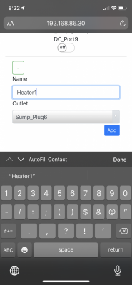
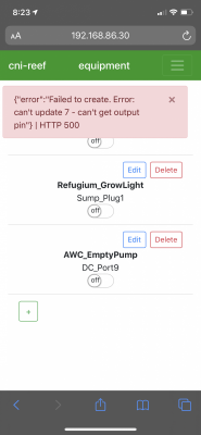
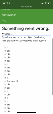
Having some issues with HS300.

I had the HS300 setup and Reef-pi controlling a single plug as a test. Then I powered off the HS300 to mount it, now I get errors in reef-pi when trying to add the other plugs and control the previously working plug.

I tried restarting the reef-pi and also checked the IP is the same on the hs300.

screenshots attached:

EEB27AF4-68D9-43DE-ABED-78EA995A1142.png 9CB1D46D-1CF2-4373-84B9-45A4CC367D39.png E4EFBAE5-DD64-4A8A-9584-9D9AE12C8540.png
 
OP
OP
Ranjib

Ranjib

7500 Club Member
View Badges
Joined
Apr 16, 2016
Messages
9,848
Reaction score
17,081
Location
Pleasant Hill, Concord
Rating - 0%
0   0   0
@Ranjib

This may sounds as a dumb question but how can I connect the ph board.

My Pi setup is using the lighting controller for 3 mars aqua as per adafruit guides. However, the PCA9685 breakout board is connected to SCL and SDA pin of the Pi.

I want to add ph monitoring to my reefpi but before getting the specific board, I want to make sure I can actually connect it.

It is my understanding that the ph board connect to SDA/SCL pin on the pi as well. How can I do this since they are already used by the PCA9685? Can I use the SDA/SCL on the opposite side of the PCA? or split the connection on the Pi pin?

Thank you
I2c is a bus you can connect multiple devices on the same soda/scl pins. Adafruit pca9685 breakout has i2c pin as well as 5v/gnd pins on the other end, connect ph probe with those pins
 

HAVE YOU EVER KEPT A RARE/UNCOMMON FISH, CORAL, OR INVERT? SHOW IT OFF IN THE THREAD!

  • Yes!

    Votes: 32 45.7%
  • Not yet, but I have one that I want to buy in mind!

    Votes: 9 12.9%
  • No.

    Votes: 26 37.1%
  • Other (please explain).

    Votes: 3 4.3%
Back
Top