reef-pi :: An opensource reef tank controller based on Raspberry Pi.

GaryE

Well-Known Member
View Badges
Joined
Mar 12, 2020
Messages
992
Reaction score
1,385
Location
Coatesville, Indiana
Rating - 0%
0   0   0
Has anyone had any issues with running more than two temp probes? I wanted to run 5 of them but seems to cause issues they keep faulting or not connecting at all? Is there a limit to the length? I would say my longest one is about 20' away. i had the same issue with my older pie also and just went down to running two but with my new build I have added a frag tank and also a mixing station temp as well as house temp.

I have four. One in my tank, one in my sump, one on the pie hat and one on my mosfet board. All work well.

IMG_20200403_182541.jpg
 

Bliff

New Member
View Badges
Joined
Apr 6, 2020
Messages
18
Reaction score
41
Rating - 0%
0   0   0
I have four. One in my tank, one in my sump, one on the pie hat and one on my mosfet board. All work well.

IMG_20200403_182541.jpg

What have you got going on in there? It looks like several mosfets, so I'm guessing you have a few PWMs? Is that the relay in the bottom left side of the photo?
 

Bliff

New Member
View Badges
Joined
Apr 6, 2020
Messages
18
Reaction score
41
Rating - 0%
0   0   0
Looks good, Welcome to R2R...looks like a good start!

:)
Thank you :).

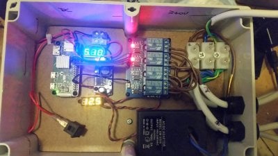
I've realised that this is an older progress photo. The input AC line is now black, and comes in through a cable gland like the outputs. The power switch and some status LEDs are planned, but I haven't cut ports yet because I'm waiting on some printable vinyl adhesive paper so I can make a nice front label. I'm also waiting on label tape so I can properly label the "AC 240V here there be dragons" area.
 

GaryE

Well-Known Member
View Badges
Joined
Mar 12, 2020
Messages
992
Reaction score
1,385
Location
Coatesville, Indiana
Rating - 0%
0   0   0
What have you got going on in there? It looks like several mosfets, so I'm guessing you have a few PWMs? Is that the relay in the bottom left side of the photo?

Well, on the proto pi hat, I have the ULN2803A to control the relays in my crappy home built power strip.
IMG_20200308_132949.jpg


There is also a DS18B20 temp sensor on board.

On the long proto board sitting at an angle (thanks small box), there are 6 mosfets and a DS18B20 with 4 headers for external sensors. I added LED's to the mosfet circuits to get a quick visualization on them. channel 4 doesn't light up. Not sure why, not interested in pulling it apart to figure it out right now.

no, that is not a relay. That's just an input power connector on the pca9685 breakout board.

I also have a header with jumpers to switch each mosfet from 12 to 24 volt output to control a variety of different devices.

This is an early pic of the board.
IMG_20200330_212425.jpg


Once the shutdown is over I will be sending off my files to get a perm board made. All of the discretes will be smd and will include buck converters on board for 12 and 5 volt, ULN2830A on board, pca9685 on board, along with dosing, ATO and pH monitoring.

I like the other board designs I have seen, however, they don't include some of the features I want, so I'm working on my own.
 
OP
OP
Ranjib

Ranjib

7500 Club Member
View Badges
Joined
Apr 16, 2016
Messages
9,848
Reaction score
17,081
Location
Pleasant Hill, Concord
Rating - 0%
0   0   0
Anyhow. Thanks to the devs and all the folks that have put together this awesome system. I've built my reef-pi and so far, it's been quite an approachable project.
I went with a LM2596 DC-DC buck converter and used a 12V 2.1A wall wart as the main power supply.
Those LED voltage meters are entirely superfluous, and I had them because they were impulse $1 buys from Aliexpress and looked nifty, so I had a few sitting around. I left them in for bling reasons.

Things Learned
If I were doing this from scratch, I'd consider using an external pack and adding a 12V input socket, since this is an IP68 enclosure, so things might get a lttle warm inside. It does seem to radiate some heat via the side wall though. I've considered using a small internal fan, just to circulate more air inside the case and therefore help to convect heat out through the other walls.

If you let your 6yo see the reef-pi control panel on their tablet, they will test how quickly all your relays can cycle (quite quickly, I found).

To Do
I have set up a PWM controlled LED, and it all worked as it should. That's not in this box though. What I'd like to make is a PWM controlled LED light batten entirley from DIY. I have some 10W, 12V LED modules. As I understand it, I would be using a power MOSFET with logic level gate driven directly from the PWM pin (does that need an RP protection diode?). I read in the light controller guide that some folks are making exactly that, but this is a very long thread and I haven't seen anything about that so far.
Is there another thread out there with this discussion? I'm a little stuck for search keywords.

Also, is there a specific thread/bug tracker for feature requests/suggestions? Is that this thread?

20200403_213620.jpg
Thank you for sharing your lessons. 6y old makes the best helping hand :)
 
OP
OP
Ranjib

Ranjib

7500 Club Member
View Badges
Joined
Apr 16, 2016
Messages
9,848
Reaction score
17,081
Location
Pleasant Hill, Concord
Rating - 0%
0   0   0
Has anyone had any issues with running more than two temp probes? I wanted to run 5 of them but seems to cause issues they keep faulting or not connecting at all? Is there a limit to the length? I would say my longest one is about 20' away. i had the same issue with my older pie also and just went down to running two but with my new build I have added a frag tank and also a mixing station temp as well as house temp.
There’s an epic post on this subject by @Erica-Renee . There are length related nuances and also different manufacturer offers different quality which can complicate things. Sometime you have to adjust the resistor threshold (and use 5 or 1k ohm ) . Search on google about multiple ds18b20 with raspberry pi and you should find useful information
 

Dave's Reef

Active Member
View Badges
Joined
Nov 4, 2018
Messages
102
Reaction score
150
Rating - 0%
0   0   0
There’s an epic post on this subject by @Erica-Renee . There are length related nuances and also different manufacturer offers different quality which can complicate things. Sometime you have to adjust the resistor threshold (and use 5 or 1k ohm ) . Search on google about multiple ds18b20 with raspberry pi and you should find useful information
Thanks I wasn't able to fine his thread but after some Googleing I did find out that you can either change the resistor or use 5v instead of 3.3v to power the probe I'll give both a try and see what works better. I just not sure why it worked fine on the bench test but doesn't now only difference that I can think of is i used cat6 patch cord for the testing and now its jacks installed in the wall maybe the additional connections is causing some loss
 

drbogger

Active Member
View Badges
Joined
Apr 24, 2019
Messages
165
Reaction score
132
Location
Ballston Spa, New York
Rating - 0%
0   0   0
How do I setup Automatic Water Changes to use ATO Sensors?

I have 2 Optical Sensors, one as high water level, and one as low water level. (The low water level sensor is only used for water changes).

I have 2 pumps, one drain pump, and one fill pump. (Both are listed under the "Equipment Tab")

I want to trigger the water change from a "timer", and I want the process to be as follows:

1. Turn on the "Drain Pump" to drain the water until water level triggers the "low water level" sensor.
2. Then turn on the "Fill Pump" until the water level triggers the "high water level" sensor.

How do I go about doing this?
 

Freccialata

Community Member
View Badges
Joined
Jan 31, 2020
Messages
53
Reaction score
98
Location
Rome (Italy)
Rating - 0%
0   0   0
Hi all... and Happy Easter everyone!!!

I created an adafruit.io account.
At the moment reef-pi seems to forward 4 feeds to my account:
- system-load5;
- system-memused;
- temperature-header;
- temperature-reading.

The temperature-header feed is sent only at the begenning, when I setup the adafruit account on reef-pi. After that, no other data arrive on my adafruit account.

In the errors I can find this logs:

Apr 12 08:42:41
{"error":"not found - that is an invalid URL, please check the API documentation at https://io.adafruit.com/api/docs to make sure your URL is correct"}

Apr 12 08:42:40
{"error":"not found - that is an invalid URL, please check the API documentation at https://io.adafruit.com/api/docs to make sure your URL is correct"}

Apr 12 08:42:41
{"error":"not found - API documentation can be found at https://io.adafruit.com/api/docs"}

I have 2 questions:

1) How can I solve the problem?
2) Is it possible to setup which feeds I want to send to my account (i.e.: Can I setup to forward only the temperature-reading feed)?

Thank you in advance for your answers.
 
OP
OP
Ranjib

Ranjib

7500 Club Member
View Badges
Joined
Apr 16, 2016
Messages
9,848
Reaction score
17,081
Location
Pleasant Hill, Concord
Rating - 0%
0   0   0
Hi all... and Happy Easter everyone!!!

I created an adafruit.io account.
At the moment reef-pi seems to forward 4 feeds to my account:
- system-load5;
- system-memused;
- temperature-header;
- temperature-reading.

The temperature-header feed is sent only at the begenning, when I setup the adafruit account on reef-pi. After that, no other data arrive on my adafruit account.

In the errors I can find this logs:

Apr 12 08:42:41
{"error":"not found - that is an invalid URL, please check the API documentation at https://io.adafruit.com/api/docs to make sure your URL is correct"}

Apr 12 08:42:40
{"error":"not found - that is an invalid URL, please check the API documentation at https://io.adafruit.com/api/docs to make sure your URL is correct"}

Apr 12 08:42:41
{"error":"not found - API documentation can be found at https://io.adafruit.com/api/docs"}

I have 2 questions:

1) How can I solve the problem?
2) Is it possible to setup which feeds I want to send to my account (i.e.: Can I setup to forward only the temperature-reading feed)?

Thank you in advance for your answers.
These errors are from UI or systemd logs? Check your feed names. If they contain space, that can cause this.
https://github.com/reef-pi/reef-pi/issues/1105
 

Freccialata

Community Member
View Badges
Joined
Jan 31, 2020
Messages
53
Reaction score
98
Location
Rome (Italy)
Rating - 0%
0   0   0
OP
OP
Ranjib

Ranjib

7500 Club Member
View Badges
Joined
Apr 16, 2016
Messages
9,848
Reaction score
17,081
Location
Pleasant Hill, Concord
Rating - 0%
0   0   0
Thanks for the answer.
These errors are from UI (configuration --> Errors).
I know that feed names can't contain space... I have named them without any space.
Can you post a screen shot? The UI should show the feedname.
 

drbogger

Active Member
View Badges
Joined
Apr 24, 2019
Messages
165
Reaction score
132
Location
Ballston Spa, New York
Rating - 0%
0   0   0
How do I setup Automatic Water Changes to use ATO Sensors?

I have 2 Optical Sensors, one as high water level, and one as low water level. (The low water level sensor is only used for water changes).

I have 2 pumps, one drain pump, and one fill pump. (Both are listed under the "Equipment Tab")

I want to trigger the water change from a "timer", and I want the process to be as follows:

1. Turn on the "Drain Pump" to drain the water until water level triggers the "low water level" sensor.
2. Then turn on the "Fill Pump" until the water level triggers the "high water level" sensor.

How do I go about doing this?

My questions always get left behind :confused:
 

Michael Lane

Well-Known Member
View Badges
Joined
Aug 11, 2018
Messages
677
Reaction score
1,123
Rating - 0%
0   0   0
Well I figured out the ribbon cable, helps to send the #9 pin (v+) to #5 on the connector end, once you do that it all works, such a Doh! moment. Sorry to clutter up the forum for real issues, now to go figure out what to do about ATO and all my other pressing issues.

@Michael Lane I am looking at the Mars aqua for lighting, I know I saw some posts that detailed the connector piece in the lights but unable to find it. If you have that handy I would appreciate it, I think you also used mini xlr connectors for the light portion also, is that correct?

Hope everyone is staying safe and doing well!
:)

I think I need to go start my build thread, here is close to a latest picture, I have the back painted black now but close to where I am at the moment.
IMG_20200403_164122.jpg
That looks really good, especially if you'll be able to use that drawer.

I've used a bunch of the mini-xlr connectors. I like them, but they are a bit expensive. I'm not sure I understand what yo mean about the Mars Aqua light connectors, but the images in this post might show what you are looking for.
 

Michael Lane

Well-Known Member
View Badges
Joined
Aug 11, 2018
Messages
677
Reaction score
1,123
Rating - 0%
0   0   0
Well I figured out the ribbon cable, helps to send the #9 pin (v+) to #5 on the connector end, once you do that it all works, such a Doh! moment. Sorry to clutter up the forum for real issues, now to go figure out what to do about ATO and all my other pressing issues.

@Michael Lane I am looking at the Mars aqua for lighting, I know I saw some posts that detailed the connector piece in the lights but unable to find it. If you have that handy I would appreciate it, I think you also used mini xlr connectors for the light portion also, is that correct?

Hope everyone is staying safe and doing well!
:)

I think I need to go start my build thread, here is close to a latest picture, I have the back painted black now but close to where I am at the moment.
IMG_20200403_164122.jpg
There are also 2 kinds of DB9 adapters and they have different pin-outs on the female side. This is the kind that I've used.
1586707521139.png


The smaller connectors doesn't work unless you pop out some pins and reconnect them differently. I can't remember which it was, but I can try to dig it back out if you need.
1586707628255.png
 

bishoptf

Valuable Member
View Badges
Joined
Jan 1, 2019
Messages
1,349
Reaction score
1,724
Location
Missouri
Rating - 0%
0   0   0
That looks really good, especially if you'll be able to use that drawer.

I've used a bunch of the mini-xlr connectors. I like them, but they are a bit expensive. I'm not sure I understand what yo mean about the Mars Aqua light connectors, but the images in this post might show what you are looking for.

Yup that was the one I was looking for, I am going to go with JST-SM connectors vs the mini xlr, I almost went with Midi and still might change my mind but my thought was to have a female to female connector back to back through a small hole, planning on doing that with my connections coming out of my reef-pi. I purchased a JST crimper and SM and XH connectors so I can make jumpers a certain length etc. Will see how it works out, can always go to plan B or C...lol

:)
 

bishoptf

Valuable Member
View Badges
Joined
Jan 1, 2019
Messages
1,349
Reaction score
1,724
Location
Missouri
Rating - 0%
0   0   0
There are also 2 kinds of DB9 adapters and they have different pin-outs on the female side. This is the kind that I've used.
1586707521139.png


The smaller connectors doesn't work unless you pop out some pins and reconnect them differently. I can't remember which it was, but I can try to dig it back out if you need.
1586707628255.png

That picture makes a lot more sense I though I had fried the uln2803 etc, I ended up just re-soldering the end to move that one connection, never figured out how to take apart an IDC connector, once they go together they are done. I have some new shells and connectors to customize length, planning on just soldering it up, bought a new small gauge wire stripper...Whoo hooo, more tools :)
 

robsworld78

Well-Known Member
View Badges
Joined
Feb 14, 2020
Messages
985
Reaction score
1,325
Location
Edmonton, Canada
Rating - 0%
0   0   0
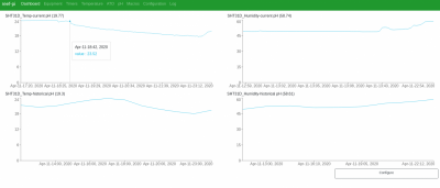
SHT31D Humidity sensor . Work in progress driver in reef-pi. It exposes two analog inputs, channel 0 represent temperature (in Celsius) and channel 1 relative humidity.

sht31d.png

That sensor is pretty expensive, have you thought about the DHT22?

Also the less I2C devices the better everyone will be. ;)
 
Back
Top