reef-pi :: An opensource reef tank controller based on Raspberry Pi.

robsworld78

Well-Known Member
View Badges
Joined
Feb 14, 2020
Messages
985
Reaction score
1,325
Location
Edmonton, Canada
Rating - 0%
0   0   0
As Ranjib said, reef-pi is quite a bit different from arduino, but you can actually run it on Windows depending on what features you are interested in testing.

I typically use VS Code on Windows for reef-pi development. Obviously, I can't interact with gpio or i2c, but we have mock drivers in dev mode that provide some insight into what would happen on actual hardware.

It's easy to cross compile with go, so you can build your changes and copy them to the rpi and try it out on the actual hardware. The cycle isn't quite as quick as arduino, but it's possible.

This sounds good, I don't care to access the gpios.

Are you running something like xampp for the database?

Any special plugins for VS needed?

For your pH that's nice not having ADM3260 my complaint has been cost.

For the Atlas circuit is Reef-pi sending calibration values to it or managing them like the ph-board?
 

NeonRabbit221B

2500 Club Member
View Badges
Joined
Jun 21, 2019
Messages
3,037
Reaction score
5,614
Location
Richmond, Va
Rating - 0%
0   0   0
Finally getting around to my electrical safety improvements and redundancy equipment for heating and I wanted to make sure I thought this through correctly. I have my American DJ relay board with everything except the pi's power supply plugged in (this goes to a separate outlet. I have a ground probe plugged into one of the unused channels that runs into the sump chambers of my AIO. The relay board goes into a GFCI plug and then into the wall. I can't power the pi from the relay board as the always on plug is dead as of now.

Additionally I have an issue where I have an electrical outlet behind the cabinet the tank sits on. If my tank were to shatter it could start a fire... No equipment is plugged in but I was wondering if it would be a good idea to 3D print some type of cover.
 

Bigtrout

Valuable Member
View Badges
Joined
Dec 16, 2018
Messages
1,189
Reaction score
2,826
Rating - 0%
0   0   0
Finally getting around to my electrical safety improvements and redundancy equipment for heating and I wanted to make sure I thought this through correctly. I have my American DJ relay board with everything except the pi's power supply plugged in (this goes to a separate outlet. I have a ground probe plugged into one of the unused channels that runs into the sump chambers of my AIO. The relay board goes into a GFCI plug and then into the wall. I can't power the pi from the relay board as the always on plug is dead as of now.

Additionally I have an issue where I have an electrical outlet behind the cabinet the tank sits on. If my tank were to shatter it could start a fire... No equipment is plugged in but I was wondering if it would be a good idea to 3D print some type of cover.
Dont print a cover for the outlet...just go get an outdoor bubble cover. If something happens a weatherproof cover is UL listed.

Gfci is always wise around water. Some people have an issue with plugging their return pumps into a gfci but if the return pump is tripping a gfci it means something is leaking to ground or the GFCI is faulty.

Many people dont know how a gfci outlet works.
It does NOT measure anything on the ground wire. What it does is measures current on the hot wire and current on the neutral wire. If that difference is 6 milliamps it trips(USA gfci). What it assumes is if the current going out on the hot is not equal to the current coming back on the neutral then it has to be leaking somewhere. And 6 milliamps is the threshold for personal safety.

Note USA gfci have a 6milliamp safety threshold. The rest of the world uses 30milliamps.
 
Last edited:

Bigtrout

Valuable Member
View Badges
Joined
Dec 16, 2018
Messages
1,189
Reaction score
2,826
Rating - 0%
0   0   0
Is there a typical module for 25kHz pwm from adafruit or sparkfun? reef-pi 3 reworked the way drivers are implemented, so it might be reasonable to add some new hardware support.
Im not sure if there are any higher frequency hobbyists modules out there. The problem becomes more expensive chips and better engineered driver designs to be able to handle the speed.
Heck I cant even find a mosfet module that will handle over 300hz correctly such that it gives you good resolution for dimming simple led circuits.
 

Bigtrout

Valuable Member
View Badges
Joined
Dec 16, 2018
Messages
1,189
Reaction score
2,826
Rating - 0%
0   0   0
Time to upgrade the Pi 3B. Gonna wait for Amazon pricing to catch up to shave off shipping.
Nice if you want to upgrade but not necessary. My build has just about everything and plugs along nicely on a lowly pi zero w. Amazing what 10 dollars gets you!
 

AbjectMaelstroM

Valuable Member
View Badges
Joined
Jul 21, 2019
Messages
1,530
Reaction score
1,811
Location
RVA
Rating - 100%
1   0   0
Nice if you want to upgrade but not necessary. My build has just about everything and plugs along nicely on a lowly pi zero w. Amazing what 10 dollars gets you!

Was going to use it for OctoPrint. 3B is probably more than my ReefPi will ever need.
 

Zippyfear

Community Member
View Badges
Joined
Apr 30, 2019
Messages
86
Reaction score
152
Rating - 0%
0   0   0
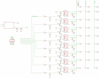
Here's an updated AC 120v - 240v power bar I've been working on for Reef-pi. I've been offering these for quite a while and stand behind it but just added a snubber to protect the relays from inductive loads such as motors and added a DB9 socket to match the Reef-pi controller so you only need one cable to controller.

It was designed to be wire free internally, the AC outlets are held firmly in place by a strong 3D printed plate and soldered directly to the board, the 5th image is what you have when its fully assembled. Then it easily drops in the case and is secured with 17 screws overall.

The power bar has an internal 120v - 240v AC-DC module which powers the relays. If Reef-pi is turned off or DB9 is unplugged all outlets turn off.

In the near future I plan to offer a small module that will add an emergency power outage feature. This will plug into the power bar DB9 and have dip switches so you can set each outlet to go to a specific mode if power to controller is lost or DB9 is unplugged. For example you could have outlet 1, 3 and 7 stay on and the remaining turn off. You could also plug something into any outlet and it will only turn on if power goes out or DB9 is unplugged. If you plug the power bar into a UPS you'll have an emergency backup mode for power outages and no need to keep the controller running under battery power.

As you can see this board has North America outlets but soon I will have a version with Australian plugs that work for many countries and another with the large universal outlets to cover the rest. I'm planning to run a Kickstarter soon if any one is interested. If you already have Reef-pi running you can get a DB9 to screw terminals adapter so it would connect easy to your system.

You can also solder wire to the pads on the circuit board and use your own outlets.

I messed up the board so had to put relays on top, I wanted them on the other side of board. Those and the other components will all be on the other side which trim about 14mm off the height of the case. And in the large image the outlets are supposed to be flush with the top but I messed up and ran out of filament, SMH...

US_power_bar_clips.jpg


power_bar_schematic.png

If you only need 8 wires, you should change the design to just use Cat 5e cables.. much cheaper and easier and more readily available for most everyone
 
OP
OP
Ranjib

Ranjib

7500 Club Member
View Badges
Joined
Apr 16, 2016
Messages
9,848
Reaction score
17,081
Location
Pleasant Hill, Concord
Rating - 0%
0   0   0
Finally getting around to my electrical safety improvements and redundancy equipment for heating and I wanted to make sure I thought this through correctly. I have my American DJ relay board with everything except the pi's power supply plugged in (this goes to a separate outlet. I have a ground probe plugged into one of the unused channels that runs into the sump chambers of my AIO. The relay board goes into a GFCI plug and then into the wall. I can't power the pi from the relay board as the always on plug is dead as of now.

Additionally I have an issue where I have an electrical outlet behind the cabinet the tank sits on. If my tank were to shatter it could start a fire... No equipment is plugged in but I was wondering if it would be a good idea to 3D print some type of cover.
GFCI and any outdoor bubble cover is better than 3d printed. Anything that requires fire or electrical safety, are better (economical and tested) with off the shelf items (from homedepot or lowes).

GFCI is a pretty robust solution , as @Bigtrout mentioned, not only where you have potential fire/water hazard, but also cases where its open ground. Something I learned recently during home purchase. The local code allows GFCI as workaround for openground situations.
 

robsworld78

Well-Known Member
View Badges
Joined
Feb 14, 2020
Messages
985
Reaction score
1,325
Location
Edmonton, Canada
Rating - 0%
0   0   0
If you only need 8 wires, you should change the design to just use Cat 5e cables.. much cheaper and easier and more readily available for most everyone

Unfortunately 9 wires are needed, 8 relays + one for a common GND. I considered only have 7 outlets switch but last minute changed to all 8, maybe 7 is better.
 

babrooks

New Member
View Badges
Joined
Feb 28, 2020
Messages
22
Reaction score
43
Rating - 0%
0   0   0
I'm not sure if there is. I've seen a couple of other pwm boards on Adafruit but couldn't find any details on frequency in the specs. I've never used the PCA9685 board before but is there a way to lower the resolution and push up the frequency that way?
I was actually a bit surprised by the lack of options there are for fan control when it comes to hardware. Maybe it's because its mainly done via a motherboard of a pc.

It would be nice to have some hardware support for pwm fan control if there is a suitable board for it. Variable fan speed might not be critical for a reef but it could make for better chiller options and control. Bigger fans on lower rpms means less noise but with the possibility to kick it up when the need is greater.

You could use an arduino board to read the PWM signal from the pi and then output it at higher frequency to the fans. By adjusting the prescaler you can set the output frequency to about 25khz. I did this with a nano to modify the signal from a bluefish controller for fans on my DIY light fixture.

(Planning to switch the light over to my reef-pi eventually :)


Michael Lane

Well-Known Member
View Badges
Joined
Aug 11, 2018
Messages
677
Reaction score
1,123
Rating - 0%
0   0   0
This sounds good, I don't care to access the gpios.

Are you running something like xampp for the database?

Any special plugins for VS needed?

For your pH that's nice not having ADM3260 my complaint has been cost.

For the Atlas circuit is Reef-pi sending calibration values to it or managing them like the ph-board?
There's no need for xampp or anything like that. reef-pi is self hosting, so you don't need server. In general, you just need go and node. We have a dev setup guide that shows dependencies. I think the makefile may have changed since the last update, but I can help you work through it if you give it a try and find problems. That would also help identify what needs to be updated.

For VS Code, I don't recall which plugins I enabled, but it recommended a bunch of stuff and I installed the ones that seemed like they would be helpful (go and react plugins).

We were sending calibration to the EZO module In previous versions of reef-pi, but removed it in order to implement calibration in reef-pi.
 

robsworld78

Well-Known Member
View Badges
Joined
Feb 14, 2020
Messages
985
Reaction score
1,325
Location
Edmonton, Canada
Rating - 0%
0   0   0
There's no need for xampp or anything like that. reef-pi is self hosting, so you don't need server. In general, you just need go and node. We have a dev setup guide that shows dependencies. I think the makefile may have changed since the last update, but I can help you work through it if you give it a try and find problems. That would also help identify what needs to be updated.

For VS Code, I don't recall which plugins I enabled, but it recommended a bunch of stuff and I installed the ones that seemed like they would be helpful (go and react plugins).

We were sending calibration to the EZO module In previous versions of reef-pi, but removed it in order to implement calibration in reef-pi.

Right on, thanks for the link and info, that should get me going and that's what I was hoping to hear about calibration.

The other day I setup my pH circuit like Atlas, it works now with the Atlas sketches but I get a strconv.ParseFloat error on Reef-pi. I found the EZO driver and the read function but not sure where the parse happens so can't figure out what it expects.

strconv.ParseFloat {"error":"strconv.ParseFloat: parsing
\"7.26\\x00xxxxxxxxxxxxxxxxxxxxxxxxx\": invalid syntax"} | HTTP 404

You can see the pH is there but something isn't right. This is what I'm sending to Reef-pi, any ideas what I'm missing?

computerdata[0] = '7';
computerdata[1] = '.';
computerdata[2] = '2';
computerdata[3] = '6';
Wire.write(1); // byte
Wire.print(computerdata); // char array
Wire.write(0); // byte
 

Mandelstam

Well-Known Member
View Badges
Joined
Oct 29, 2017
Messages
688
Reaction score
1,119
Location
Malmö, Sweden
Rating - 0%
0   0   0
You could use an arduino board to read the PWM signal from the pi and then output it at higher frequency to the fans. By adjusting the prescaler you can set the output frequency to about 25khz. I did this with a nano to modify the signal from a bluefish controller for fans on my DIY light fixture.

(Planning to switch the light over to my reef-pi eventually :)


Yes that was one of the options I was considering. Glad to hear that it works!
 

Michael Lane

Well-Known Member
View Badges
Joined
Aug 11, 2018
Messages
677
Reaction score
1,123
Rating - 0%
0   0   0
Right on, thanks for the link and info, that should get me going and that's what I was hoping to hear about calibration.

The other day I setup my pH circuit like Atlas, it works now with the Atlas sketches but I get a strconv.ParseFloat error on Reef-pi. I found the EZO driver and the read function but not sure where the parse happens so can't figure out what it expects.

strconv.ParseFloat {"error":"strconv.ParseFloat: parsing
\"7.26\\x00xxxxxxxxxxxxxxxxxxxxxxxxx\": invalid syntax"} | HTTP 404

You can see the pH is there but something isn't right. This is what I'm sending to Reef-pi, any ideas what I'm missing?

computerdata[0] = '7';
computerdata[1] = '.';
computerdata[2] = '2';
computerdata[3] = '6';
Wire.write(1); // byte
Wire.print(computerdata); // char array
Wire.write(0); // byte
It looks like you are missing the string terminator. You may need something like computerdata[4] = '\0';
 

robsworld78

Well-Known Member
View Badges
Joined
Feb 14, 2020
Messages
985
Reaction score
1,325
Location
Edmonton, Canada
Rating - 0%
0   0   0
It looks like you are missing the string terminator. You may need something like computerdata[4] = '\0';

'\0' and 0 appear to do the same, tried '\r' '\n' '\0' and 0 in all combinations.

I thought the x's might be extra bytes but when I do Wire.print(computerdata,2); it only sends the first 2 bytes, the same amount of x's still follow in error so it's only sending what it should.

If there's one terminator it shows.

\"7.26xxxxxxxxxxxxxxxxxxxxxxxxx\": invalid syntax"}

every extra terminator adds \\x00 after 7.26

If I remove Wire.write(1); I get an execute error so it's handling that ok.
 

Des Westcott

Well-Known Member
View Badges
Joined
May 29, 2018
Messages
646
Reaction score
1,035
Location
Durban - South Africa
Rating - 0%
0   0   0
Macro and Timer update:

I have a pair of Macros that when I run manually, I run the first one ((1) - about 60minutes long) and about 2 minutes I trigger a second one (2) which is about 5 minutes long. When run manually, they run "concurrently" / at the same time.

On the back of this success, I wrote another Macro (3) to execute (1) and then 2 minutes later, (2) but (2) only executes 2 minutes after (1) finishes. I did this to simplify running (3) on a timer.

For various reasons, I want to keep (1) and (2) separate to be able to run individually as I want and be able to vary / add steps / times in (3) without directly affecting (1) and (2). I could just create one Macro combining (1) and (2), which will achieve the same goal.

My work-around to the above is to have two timers triggering (1) and then (2) two minutes apart.

Once again, just documenting my experiences in case someone else is battling with the same.
 

Freccialata

Community Member
View Badges
Joined
Jan 31, 2020
Messages
53
Reaction score
98
Location
Rome (Italy)
Rating - 0%
0   0   0
Hi all.
I still have problem with temperature sensor.
Which is exactly the 4.7k resistor to use to connect the red and yellow cable?
I see there are different kinds of resistor... blue (or ciano) type and light brown tipe.... which is the right I should use?

Thank you in advance for your answer.
 
Back
Top