reef-pi :: An opensource reef tank controller based on Raspberry Pi.

marekd1

Active Member
View Badges
Joined
Dec 24, 2019
Messages
133
Reaction score
200
Rating - 0%
0   0   0
The system would be more reliable with coax extensions vs I2C runs. I2C was never designed to leave the circuit board as the protocol has no error proofing built in and noise is it's worse enemy but yeah using these buffers go a long way.
Agreed that I2C was never designed to leave the circuit board but for non critical applications like parameter measurement this could be sufficing. Keeping in mind noise sensitivity and lack of error proofing real implementations success will vary. What would be nice is ability to connect reef-pi with say Arduino Mega over serial and this would allow easy remote I/O and I2C expansion with many more I/O lines than available on Raspberry Pi.

Ranjib mentioned in the past posts that this may become reality but it all takes time. I wish I could contribute on the software side but I am purely hardware guy with some software skills. :(
 

Matevz Savarin

Active Member
View Badges
Joined
Dec 5, 2018
Messages
209
Reaction score
163
Rating - 0%
0   0   0
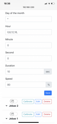
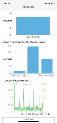
Is this a bug in dashboard or my pump was working at 0:00 for 30s ? I have it set up for 10s at 80% thats 8ml of fluid 4 times a day..
But dashboard says it was working 30s.

BC1377BE-5684-425C-84E3-EE85C682AEBB.png 628D93AE-9958-44D3-9A9D-305EB73B719C.png
 

cwalton00

Active Member
View Badges
Joined
Jan 19, 2017
Messages
324
Reaction score
249
Rating - 0%
0   0   0
Spent the last couple of weeks sourcing and building my reef-pi. Very excited to have it all up and running. Question though: I have the optical sensor for ATO and have a float installed just above the optical level as a back up. What's the recommended way of configuring the optical as primary input control for ATO, while using the float as an override to shut off the ATO? Can that be set up with the macro functionality?

IMG_20200213_000032.jpg
IMG_20200213_050951.jpg
what is this case?
 

elysics

Valuable Member
View Badges
Joined
Jan 15, 2020
Messages
1,591
Reaction score
1,590
Rating - 0%
0   0   0
what is this case?

google for waterproof transparent junction box, theres thousands of them in all possible sizes. Just dont expect the IP waterproofing ratings to not be lies if you buy a cheap one, though you probably wouldn't go through the effort to keep those ratings anyway.

Consider whether you actually want to see the innards though. Depending on how clean your wiring is and how many components with LEDs are in there, it can look cool and techy or like an annoying blinking entangled mess. I chose the plain grey, non-transparent version.
 
Last edited:

Des Westcott

Well-Known Member
View Badges
Joined
May 29, 2018
Messages
646
Reaction score
1,035
Location
Durban - South Africa
Rating - 0%
0   0   0
Spent the last couple of weeks sourcing and building my reef-pi. Very excited to have it all up and running. Question though: I have the optical sensor for ATO and have a float installed just above the optical level as a back up. What's the recommended way of configuring the optical as primary input control for ATO, while using the float as an override to shut off the ATO? Can that be set up with the macro functionality?

IMG_20200213_000032.jpg
IMG_20200213_050951.jpg
I also have a safety float switch above my normal running level. I run this completely separately from reef-pi and use it to cut power to all my ATO related 12V systems
 

Matevz Savarin

Active Member
View Badges
Joined
Dec 5, 2018
Messages
209
Reaction score
163
Rating - 0%
0   0   0
Cwaltoon00 I gave up on macros for ato safety function. Just didnt work. Just do it like Des westcott said, put one float above water line and if relay or sensor fails, float will cut off power to ato pump. This is 100% safety feature, regardless reefpi and outlets..
 

marekd1

Active Member
View Badges
Joined
Dec 24, 2019
Messages
133
Reaction score
200
Rating - 0%
0   0   0
Cwaltoon00 I gave up on macros for ato safety function. Just didnt work. Just do it like Des westcott said, put one float above water line and if relay or sensor fails, float will cut off power to ato pump. This is 100% safety feature, regardless reefpi and outlets..


Hopefully no one is using the little float switches (reed magnetic switch) to switch 110V for ATO pumps as a sensor fail safe. One, you would have 110V in a salt water. Two, these were not designed to switch 110V. Always use property matched relay to switch 110V and use 12 or 24V on the relay coil through the float switch to control the relay action.

Just want to make sure no one get hurts sticking their hand in the tank and the sensor is bleeding power in to the water.
 

Bigtrout

Valuable Member
View Badges
Joined
Dec 16, 2018
Messages
1,189
Reaction score
2,826
Rating - 0%
0   0   0
Hopefully no one is using the little float switches (reed magnetic switch) to switch 110V for ATO pumps as a sensor fail safe. One you would have 110V in a salt water, two these were not designed to switch 110V. Always use property matched relay to switch 110V and use 12 or 24V on the relay coil through the float switch to control the relay action.

Just want to make sure no one get hurts sticking their hand in the tank and the sensor is bleeding power in to the water.
Great advice!!!
 

jhoop

Active Member
View Badges
Joined
Jan 10, 2014
Messages
156
Reaction score
179
Location
Cleveland Ohio
Rating - 0%
0   0   0
I am working on a second Reef-pi build. I started thinking I would use the ADJ power strip. Now they are hard to get or to expensive. I would like to control two AC power sources for an ATO toms aqualifter and pumps. It is a small tank 20 gals. I have a amazon relay board 5 volt switch. The 3.3 volts from the pi is not switching the relay. I did set up the pi hat to use the ULN2803A. I put a meter on the output and voltage goes from .6 to .8.

What is the best way to control the relay board. I read and searched all the posts just getting more confused ! Jello brain now.
 

Bigtrout

Valuable Member
View Badges
Joined
Dec 16, 2018
Messages
1,189
Reaction score
2,826
Rating - 0%
0   0   0
I am working on a second Reef-pi build. I started thinking I would use the ADJ power strip. Now they are hard to get or to expensive. I would like to control two AC power sources for an ATO toms aqualifter and pumps. It is a small tank 20 gals. I have a amazon relay board 5 volt switch. The 3.3 volts from the pi is not switching the relay. I did set up the pi hat to use the ULN2803A. I put a meter on the output and voltage goes from .6 to .8.

What is the best way to control the relay board. I read and searched all the posts just getting more confused ! Jello brain now.
Which reef pi Hat do you have?
 

marekd1

Active Member
View Badges
Joined
Dec 24, 2019
Messages
133
Reaction score
200
Rating - 0%
0   0   0
I am working on a second Reef-pi build. I started thinking I would use the ADJ power strip. Now they are hard to get or to expensive. I would like to control two AC power sources for an ATO toms aqualifter and pumps. It is a small tank 20 gals. I have a amazon relay board 5 volt switch. The 3.3 volts from the pi is not switching the relay. I did set up the pi hat to use the ULN2803A. I put a meter on the output and voltage goes from .6 to .8.

What is the best way to control the relay board. I read and searched all the posts just getting more confused ! Jello brain now.


you have two options, one use the ULN2803A with designated I/O pins on the RP to drive the relay or use PCA9685 to drive the relays over I2C. I've implemented the latter as there is too small number of I/O lines and I reserve them to be used as inputs (at least for my application) and I use PCA9685 as outputs. The benefits are that since PCA9685 are I2C you can stack as many as you may need to create as many Output control lines as you need. Second these are also PWM outputs and you can plan to use them or part (leftover as there are 16 lines per board) to control Lights or Doser, etc. This gives you flexibility to control many devices with one type of board.

As to then ULN2803 you have to make sure you are powering it with 5V and grounds need to be connected together even if you are using different power sources between the RP and ULN and relay board power. All grounds need to be together across all devices

Hopefully this helps
 
Last edited:

inktomi

ReefMan
View Badges
Joined
Feb 17, 2018
Messages
429
Reaction score
410
Location
Los Angeles, CA
Rating - 0%
0   0   0
With the Reef Pi Goby hat... I can't seem to control my ADJ strip. I've connected wires from the pins near the ULN2803 to a serial breakout board (leaving pin 9 unconnected), and I've set up Connectors for each pin in the UI mapped to Raspberry Pi IO pins. I assigned mock outlets to each Connector, but they don't seem to work.

Any ideas what I've done wrong?
IMG_20200217_161744.jpg
 

Michael Lane

Well-Known Member
View Badges
Joined
Aug 11, 2018
Messages
677
Reaction score
1,123
Rating - 0%
0   0   0
With the Reef Pi Goby hat... I can't seem to control my ADJ strip. I've connected wires from the pins near the ULN2803 to a serial breakout board (leaving pin 9 unconnected), and I've set up Connectors for each pin in the UI mapped to Raspberry Pi IO pins. I assigned mock outlets to each Connector, but they don't seem to work.

Any ideas what I've done wrong?
IMG_20200217_161744.jpg
The ADJ power strip requires V+ to be connected as well. I notice that the pin for 12v to the ADJ strip isn't connected. I believe it should connect to pin 5 on the DB-9 port.

1581986295477.png
 

inktomi

ReefMan
View Badges
Joined
Feb 17, 2018
Messages
429
Reaction score
410
Location
Los Angeles, CA
Rating - 0%
0   0   0
The ADJ power strip requires V+ to be connected as well. I notice that the pin for 12v to the ADJ strip isn't connected. I believe it should connect to pin 5 on the DB-9 port.

That was it! I was wondering if it might be something like that. Eveything works perfectly now. Onto the next thing - hooking up a meanwell PWM dimmable power supply for the lights!

Thank you again!
 

Matevz Savarin

Active Member
View Badges
Joined
Dec 5, 2018
Messages
209
Reaction score
163
Rating - 0%
0   0   0
One question guys it was written before, but I have to ask.. I am running out of pins for pwm control so can I add some extension to existing mikes hat? When I will do leds I need 9channels and I have used 4 channels so far. So I am 2 channels short. Can I use gpio headers for pwm purpose? I just need to power them with 5v and it should work? Thank you!
Btw I just adeed feeder to my pi:)
 

Bigtrout

Valuable Member
View Badges
Joined
Dec 16, 2018
Messages
1,189
Reaction score
2,826
Rating - 0%
0   0   0
One question guys it was written before, but I have to ask.. I am running out of pins for pwm control so can I add some extension to existing mikes hat? When I will do leds I need 9channels and I have used 4 channels so far. So I am 2 channels short. Can I use gpio headers for pwm purpose? I just need to power them with 5v and it should work? Thank you!
Btw I just adeed feeder to my pi:)
Id just add a pca9685 pwm board to the existing hat.
 

HAVE YOU EVER KEPT A RARE/UNCOMMON FISH, CORAL, OR INVERT? SHOW IT OFF IN THE THREAD!

  • Yes!

    Votes: 32 45.7%
  • Not yet, but I have one that I want to buy in mind!

    Votes: 9 12.9%
  • No.

    Votes: 26 37.1%
  • Other (please explain).

    Votes: 3 4.3%
Back
Top