reef-pi :: An opensource reef tank controller based on Raspberry Pi.

marekd1

Active Member
View Badges
Joined
Dec 24, 2019
Messages
133
Reaction score
200
Rating - 0%
0   0   0
BTW @Ranjib, since I've been doing Auto Water Changes, I have been wondering more and more about monitoring Salinity / SG / EC. Any idea if this could be incorporated into Reef-Pi? Is a reasonable probe / sensor even available?


Atlas Scientific has very nice stamp sensors. It would be nice if SG/ Salinity /ORP support could be added. The PH from what I understand is already supported with the Atlas Scientific board. Any possibilities of adding this devices to the support matrix?
 

marekd1

Active Member
View Badges
Joined
Dec 24, 2019
Messages
133
Reaction score
200
Rating - 0%
0   0   0
That makes sense, but I'm doubtful it would work. The DC motors have a lower threshold to turn on, and I've found that mine seem to need at least 50% to turn. I tend to tweak time and schedule in order to keep my levels where I want them, so dosing half as often would be the approach I take. Then again, I have an hourly dosing schedule now...


I've been testing with different pumps and less than 70% may have unreliable measurements. I would suggest to keep power at 80-100% and play with time. i.e. 0.5sec less to reduce the dose to less than 1ml. From my testing thus far it appears to work very well. I tried as low as 0.1sec for time and it seems to work well
 

marekd1

Active Member
View Badges
Joined
Dec 24, 2019
Messages
133
Reaction score
200
Rating - 0%
0   0   0
I'm comfortable with soldering as long as nothing is super small and closely located near other important connections... My main fear with soldering is accidentally burning something else nearby, but I'm good with basic soldering connections


Then you should have no problem. If you do not want to cut any wires you can first just disconnect the connectors for the motors from the control board and insert wires directly from the relay to the connector. The other pin on the connector would go to ground.

If you unplug the control board there is noting to blow. you will need 12V on the relay contacts to the motor and use 5V control voltage to switch the relays. since all GPIO pins are at 3.3V level you will need to most likely insert the ULN chip (as per the salve instructions) but you can also use 2n2222 as 3.3V to 5V level shifters.
 

Phildago

Well-Known Member
View Badges
Joined
Oct 11, 2019
Messages
854
Reaction score
933
Location
Broad Channel
Rating - 0%
0   0   0
Then you should have no problem. If you do not want to cut any wires you can first just disconnect the connectors for the motors from the control board and insert wires directly from the relay to the connector. The other pin on the connector would go to ground.

If you unplug the control board there is noting to blow. you will need 12V on the relay contacts to the motor and use 5V control voltage to switch the relays. since all GPIO pins are at 3.3V level you will need to most likely insert the ULN chip (as per the salve instructions) but you can also use 2n2222 as 3.3V to 5V level shifters.
Thanks for the info. So then it sounds like this is a on of switch for the motors controlled at the relay...
 

marekd1

Active Member
View Badges
Joined
Dec 24, 2019
Messages
133
Reaction score
200
Rating - 0%
0   0   0
Thanks for the info. So then it sounds like this is a on of switch for the motors controlled at the relay...


exactly…. if you want to get fancy you can also use the PCA 9685 PWM control with


motors will go directly to the l298N.

here is a good article to get familiar with how to use it.


you will need to use PWM from the PCA9685 and few GPIO pins to control direction. Same concepts as for Arduino but you would use I/O from Rasp-PI instead.
 

Phildago

Well-Known Member
View Badges
Joined
Oct 11, 2019
Messages
854
Reaction score
933
Location
Broad Channel
Rating - 0%
0   0   0
exactly…. if you want to get fancy you can also use the PCA 9685 PWM control with


motors will go directly to the l298N.

here is a good article to get familiar with how to use it.


you will need to use PWM from the PCA9685 and few GPIO pins to control direction. Same concepts as for Arduino but you would use I/O from Rasp-PI instead.
I'll give that a read through for sure and reassess what my capabilities are. I'm good with diy electronics that are all wiring, but this is my first project with programing coming into play. I'll have to learn exactly how all this stuff interacts.

I don't think I'd have any need to reverse the direction of my dosing pump, but speed control would be nice for getting it finely tuned.

Do you have any recommendations for reef pi dosing builds or should I just stick to the instructions on the reef pi web page?
 

marekd1

Active Member
View Badges
Joined
Dec 24, 2019
Messages
133
Reaction score
200
Rating - 0%
0   0   0
I'll give that a read through for sure and reassess what my capabilities are. I'm good with diy electronics that are all wiring, but this is my first project with programing coming into play. I'll have to learn exactly how all this stuff interacts.

I don't think I'd have any need to reverse the direction of my dosing pump, but speed control would be nice for getting it finely tuned.

Do you have any recommendations for reef pi dosing builds or should I just stick to the instructions on the reef pi web page?


You do not need to implement the reverse pins. Here is the guide that you can use. Since you will unplug the DC motors from the JEBAO's controller they will then plug in directly as shown here..


lmm1967

Well-Known Member
View Badges
Joined
Sep 12, 2017
Messages
563
Reaction score
848
Location
North Georgia
Rating - 0%
0   0   0
If you are comfortable with command line/computers then pi zero should be enough. You can use Kasa smart plugs (HS103, 110, 105, 300) with reef-pi.
Thank you - I've been in IT for (lets not talk about things that remind us of how old we are) - I'm quite happy in a CLI so I think an order for a pi zero w is in the very near future.
 

lmm1967

Well-Known Member
View Badges
Joined
Sep 12, 2017
Messages
563
Reaction score
848
Location
North Georgia
Rating - 0%
0   0   0
Nothing specifically for reef-pi. The pros/cons are very similar to most other projects based on Raspberry Pi. Here is the summary:
- Pizero w: cheap, smallest power footprint (140ma) & small form factor, yet powerful enough to run reef-pi. Bad for running graphics/desktop, bad for beginners (no standard USB & LAN connector)
- Pi 3/B+: Powerful enough to run desktop along side reef-pi. Ease of use for beginners because of onboard USB and LAN ports. Consume more power, takes more space and costs more.

- Pi 3 A: Somewhere in the middle.


Given this, I think its wiser to discuss what your computer skill levels are and what type of build you are aiming for, along side any monetary constrain (though i think this is perhaps the least concerning part) for deducing the best choice for your build

Monetary constraints - HA - this is reefing! In all seriousness - I have a bunch of Apex stuff running 3 tanks right now, a bunch of almost brand new GHL stuff running 2 tanks. All that is going to be sold - I'm tired of the lackluster support from companies that believe THEY are the customer. Ask either of those companies a question that they dont' have a solid answer for and they immediately move into a mode of telling you to convince them why you would want to do what you are asking them if they can achieve. I simply don't get it.

That's a lot of words to say budget is not my top priority.

Computer skills - sr.level network engineer, sr. level sysadmin (Win & Linux), technical manager for IT architects. I'm a total hack at writing code though. I can snag scripts, automations from github or other online resources - and usually modify them to fit my needs. I don't write code from scratch.

I solder like a 12 year old - it'll probably work but needs to be hidden cause it'll be real ugly with 10X more solder than is needed.

All that said - I'm convinced reef-pi is going to fill my needs better than what's on the market these days.
 

Bigtrout

Valuable Member
View Badges
Joined
Dec 16, 2018
Messages
1,189
Reaction score
2,826
Rating - 0%
0   0   0
Monetary constraints - HA - this is reefing! In all seriousness - I have a bunch of Apex stuff running 3 tanks right now, a bunch of almost brand new GHL stuff running 2 tanks. All that is going to be sold - I'm tired of the lackluster support from companies that believe THEY are the customer. Ask either of those companies a question that they dont' have a solid answer for and they immediately move into a mode of telling you to convince them why you would want to do what you are asking them if they can achieve. I simply don't get it.

That's a lot of words to say budget is not my top priority.

Computer skills - sr.level network engineer, sr. level sysadmin (Win & Linux), technical manager for IT architects. I'm a total hack at writing code though. I can snag scripts, automations from github or other online resources - and usually modify them to fit my needs. I don't write code from scratch.

I solder like a 12 year old - it'll probably work but needs to be hidden cause it'll be real ugly with 10X more solder than is needed.

All that said - I'm convinced reef-pi is going to fill my needs better than what's on the market these days.
The great thing is everyone fits in here. This is a great project. Everyone that builds one ends up helping the next guy. Some on here are good at computer skills and contribute in that way. Some can design new boards. Some can wrtie the code amd help there. Some are good troubleshooters and help peiple that get stuck on a build. But everyone can build a reef pi setup to fit their own aquarium. You dont even need a reef, alas im a freshwater guy who built one for a freshwater planted tank.
Ask questions. Help out when you can. Build your own controller the way you want. Theres alot of satisfaction in having your own controller that you built running your tank better than those storebought controllers could hope to.
 

Des Westcott

Well-Known Member
View Badges
Joined
May 29, 2018
Messages
646
Reaction score
1,035
Location
Durban - South Africa
Rating - 0%
0   0   0
I took some notes on setting up a pH board today, so I'll share them here too.

Verify the i2c address by running i2cdetect

image


0x40 and 0x70 are the PCA9685 PWM chip. 0x45 is the pH board.

In reef-pi, make sure pH is enabled in the Configuration | Settings tab.

image


Then, on the Configuration | Drivers tab, add a driver entry for the ph-board. The default address should be incorrect since it is already assigned to the pca9685, with both jumpers it should be 69 (0x45). reef-pi expects a decimal value instead of the hex value.

HexDecimal
0x4064
0x4165
0x4468
0x4569
image


With correct address...

image


After that, you should be able to create an Analog Input on Configuration | Connectors.

image


Finally, you can add a pH.

image

Just followed @Michael Lane directions above to set up pH. Was really easy. Thanks for sending all the goodies Michael!!!
 

Bigtrout

Valuable Member
View Badges
Joined
Dec 16, 2018
Messages
1,189
Reaction score
2,826
Rating - 0%
0   0   0
Just followed @Michael Lane directions above to set up pH. Was really easy. Thanks for sending all the goodies Michael!!!
I have found the reef pi ph board with a milwaukee probe to be very accurate. Neat to see the daily ph cycle when the lights ramp up and the plants get going and use the co2.
I can now use the amount of ph change to tell when its time to change water.
Had the ph board for half year and it hasnt changed calibration numbers yet.
 

Michael Lane

Well-Known Member
View Badges
Joined
Aug 11, 2018
Messages
677
Reaction score
1,123
Rating - 0%
0   0   0
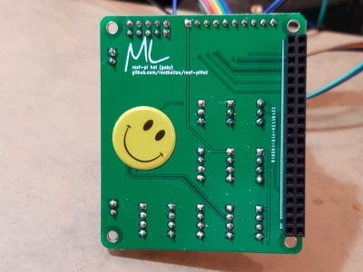
Hi, @Michael Lane, Pi-Hat pin continuity test
before i setup and test the new ras-pi with pi-HAT i tested the pins for continuity, and this is what i got
5 v pin connected properly to pH1, pH2, ATO1, ATO2, ATO3, 5v pin on GPIO breakout
ground connected properly all ground points on the board
3.3v pin NOT connected to any temp ports, or any other pin on the board
GPIO 4 connected to all temp ports
i don't know if the 3.3 v should be like this showing no continuity because of the 470k resistor or this is a bad connection
do i use this board on my new res-pi
@Alaa That sounds pretty strange. 3.3v should not be impacted by the 4.7k pull up resistor, although it may not show continuity to the 1 Wire pins. Could you post a picture of the bottom of the board?
 

Alaa

Community Member
View Badges
Joined
Nov 28, 2018
Messages
74
Reaction score
80
Rating - 0%
0   0   0
Hi, finally got my new Pi up and running
Regarding the 5v relays the diagram @Michael Lane and @Des Westcott's posted is correct and allow you to run 16 (5V) relays. However there is another way that is working also:

1- Connect a dedicated 5v power supply to the JD-VCC and ground of the relays after removing the jumper connectin JD-VCC to VCC.

2- Connect GPIO from the HAT (8 from the GPIO breakout and 8 from the ULN2803A output) to the relay boards ins (8 each),

3- Connect 5v form the HAT (the one with the GPIO breakout) to VCC that is between JD-VCC and ground on the relay boards (one v 5v from the HAT can supply both relay boards),

4- NO need to connect anything to the 12 volt power input on the HAT.

this method is better for those who has the PI-HAT and the power module in separate enclosures, as it requires only 9 lines (8 GPIO and one 5v) to each relay board,also you can work with your PI-HAT without interrupting the power module (at least the one set as NC).
 

peejay

New Member
View Badges
Joined
Nov 16, 2019
Messages
15
Reaction score
10
Rating - 0%
0   0   0
Help! I have Temperature on my dashboard and until recently it displayed from 0 up to the max temperature but it has started displaying just from min to max temperature. I am not aware of changing anything, how can I get it back to the original? Thanks.
 

Michael Lane

Well-Known Member
View Badges
Joined
Aug 11, 2018
Messages
677
Reaction score
1,123
Rating - 0%
0   0   0
Help! I have Temperature on my dashboard and until recently it displayed from 0 up to the max temperature but it has started displaying just from min to max temperature. I am not aware of changing anything, how can I get it back to the original? Thanks.
If this is a relatively new set up, then I bet the 0 is from the time before readings were coming in. The reduced range is probably being used now because all of the readings are within your defined range. If you want the range to start at 0, you should be able to just set that as the minimum instead.
 

MikeSpike

Community Member
View Badges
Joined
Jan 2, 2019
Messages
79
Reaction score
52
Rating - 0%
0   0   0
Can someone help me with ATO. Standard functionality working as it should. However the “Disable on alert” doesn’t seem to work.
I have set Alert = Yes, Disable on Alert = Yes and Alert after 15 Seconds. But pump remains on for longer than that. E.g Friday night when I was out and my ATO ran dry.
Running 2.5 (not had a chance to upgrade yet).
Any advice on getting this to work? And when it does what alert is sent? -email like with Temp? And then how is it reset to start working again?

thank you
 

raketemensch

Ape That Likes Fish
View Badges
Joined
Oct 13, 2019
Messages
378
Reaction score
478
Location
Northwest CT
Rating - 0%
0   0   0
@Alaa Des Westcott's answer is correct. I need to pull these diagrams together and post them with the FAQ.

The ATO port can accommodate multiple kinds of ATO sensors. Depending on the type of sensor, you may not have to use all pins. Let me know if it's still an issue; I can draw a wiring diagram if it would be helpful.

That would be awesome, and would go well in the FAQ :]

Since the float switch is just two wires, is it really as simple as connecting it to to two non-ground pins?
 

MikeSpike

Community Member
View Badges
Joined
Jan 2, 2019
Messages
79
Reaction score
52
Rating - 0%
0   0   0
Can someone help me with ATO. Standard functionality working as it should. However the “Disable on alert” doesn’t seem to work.
I have set Alert = Yes, Disable on Alert = Yes and Alert after 15 Seconds. But pump remains on for longer than that. E.g Friday night when I was out and my ATO ran dry.
Running 2.5 (not had a chance to upgrade yet).
Any advice on getting this to work? And when it does what alert is sent? -email like with Temp? And then how is it reset to start working again?

thank you
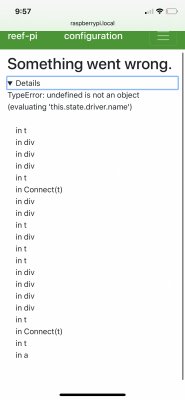
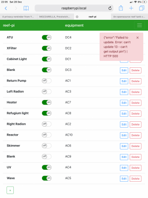
Thought it would be prudent to update to 3 this evening to try and resolve...now the whole things gone haywire.

im getting
{"error":"stats for id: '5' not found"} | HTTP 404
And on the connections tab it’s looking even worse. See screenshot. Could someone help?
Absolutely nothing works now not even turning equip on and off

39F30D26-6059-4F45-A61B-0FF20D9A6329.png A761A379-0C59-45F9-BBFE-30D2BECFC095.png
 
Last edited:
Back
Top