Greetings fellow reefers. I’m building out a new large reef tank and, in the past few days, turned my attention to programming a salt mixing and water change routine. I’ve done automatic water changes before and Apex has made it pretty simple to program a basic automatic water change but I wanted additional automation and failsafes for this system. I’ve come to subscribe to the firm belief that everything that can go wrong eventually will on a reef so I try to design backups to backups for every week point. I’m posting what I worked up for this installation for two reasons: 1) in case it helps any fellow reefer looking to do something similar (and saves you the hours I spent this past weekend debugging my first few approaches); and 2) in case anyone sees a weakness in my approach I’ve overlooked. If you do, please comment with any suggestions to improve it.
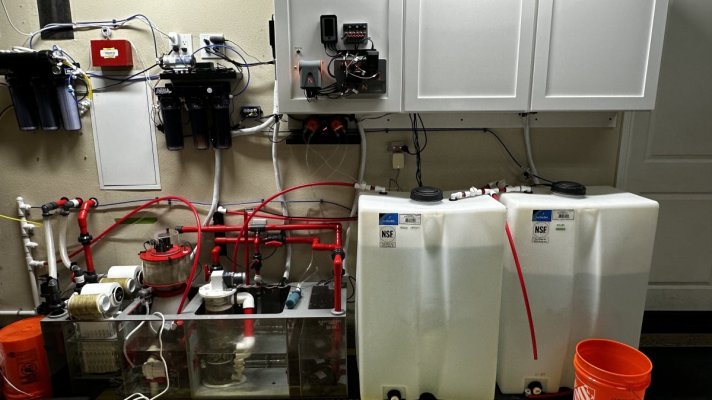
In terms of basic setup, the display tank (260 gallon) sits in a room against a wall to the garage so the sump and most support gear is in the garage right next to a hose bib (got lucky with that). So my RO/DI system, RO reservoir and salt water reservoir (each 80 gallons) are all right next to the sump. Here’s a picture of the basic layout:
I’ve already set up a basic auto top off system with a Tunze Osmolator, and installed a barrel-tender system (Buckeye Hydro) to refill the RO reservoir when it gets low without constantly cycling the RO/DI filter and magnifying the effects of TDS creep. The focus of this project was to program auto water changes in a smart way that pauses when salt water needs to be added and doesn’t resume until salinity is confirmed.
For the water change system, I have several goals/needs for the design. It needs to
In terms of hardware, the setup is pretty straightforward. In the picture above, the right reservoir is for RO/DI water. The RO unit feeds directly into that reservoir. The solenoid sitting right above the reservoir is part of the Buckeye Hydro barrel tender system that reduces TDS creep. I have a pump inside the reservoir that feeds the red PEX lines above. By turning the three ball valves on top, I can send that water either 1) through the wall into the display room to fill three dosing reservoirs in a cabinet next to the display tank; 2) into the saltwater reservoir; or 3) into the open tube in front, which I can use to pull a bucket of DI water or can connect to a longer hose to refill the ATO reservoir on my quarantine tank on the other side of the garage.
The left reservoir is the saltwater mixing reservoir. It has a couple powerheads that are always on. They are placed below the lowest level I let the reservoir drain to. There’s also a pump that feeds the PEX line coming out of the left side of the reservoir. I can use this to either add saltwater to the sump if I ever do a manual water change or can divert it to other destinations (like a bucket or hose to get it to my QT).
Ideally, I would have liked to elevate the saltwater reservoir and used a sloped bottom reservoir so I could periodically drain it entirely but this setup fit my space better. From time to time, the salt reservoir will accumulate nutrients or even algae and need to be thoroughly cleaned. I can manage it manually but the ability to fully drain it would be an improvement.
Sitting above the salt reservoir is the DOS that will do the water changes with tubes connected from the reservoir, to the sump, from the sump and to the drain. Setting up a DOS to do basic automatic water changes is relatively straightforward and there was a lot of good information out there on doing it. By far, the simplest approach is to just install it and run the Automatic Water Change Task in Apex Fusion. It walks you through the entire process pretty quickly and does the hard work. But this won’t provide the redundancy and other features I’m looking for. I wanted to try the Task Wizard so I started with this approach and found the Apex interface well thought out and easy to follow. Very quickly, it was set up to do automatic 4-gallon water changes each day.
For the additional features described above, a few more pieces of hardware and a fair amount of additional code is required. The hardware needed includes a breakout box, a momentary button to serve as an input to the BoB, two liquid level sensors (these can be the Apex optical sensors or float sensors), and two LED lights (I used the Adaptive Reef two-light module).
The logic of the system is as follows: When the saltwater reservoir is full of saltwater mixed to the proper salinity, all systems will be in “go” mode and the DOS will perform its water changes per whatever volume and timing is programmed in the Task Wizard. A green LED light mounted near the mixing station will be illuminated to show, at quick glance, that the system is working properly.
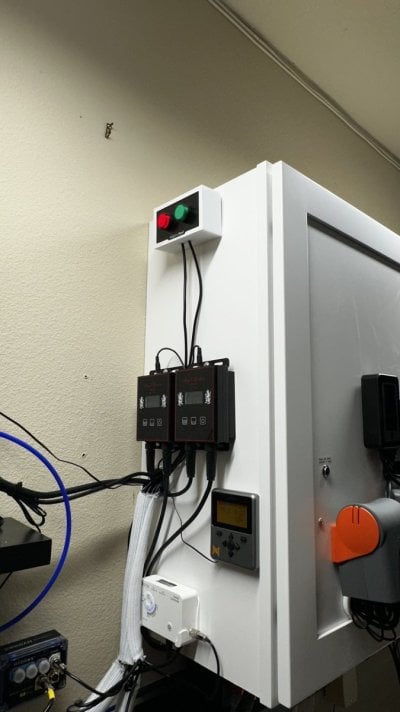
Two optical monitors (or floats) are installed in the saltwater reservoir – one low and one high. As the saltwater gets consumed and drops below the high sensor, nothing changes, but once it drops below the low sensor, the water changes are suspended, the green light turns off, a red light turns on and Apex sends me an alert that the saltwater reservoir is low.
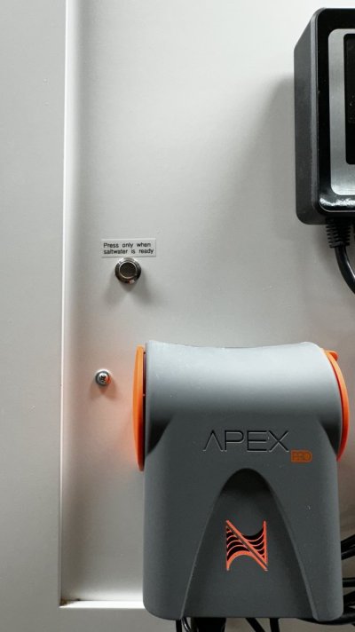
The system remains in this suspended mode until I mix up new saltwater. I haven’t found it practical to automate the actual mixing of saltwater so this is my one manual step. In my case, that means opening a ball valve and activating a pump to transfer water from the RO reservoir to the saltwater reservoir, adding salt, waiting for it to mix, and fine tuning salinity. Once I confirm the saltwater is ready, I press a momentary button. The red light turns off; the green light turns on; the DOS resumes auto water changes.
I usually mix about 70 gallons of saltwater and the low sensor is around the 8 gallon mark, so at 4 gallons per day, this gets me about two and a half weeks.
For the programming, I created three virtual outlets. One is labeled NSW_Ready and acts as the final input to the hardware confirming all systems are go. One is labeled Hi_SW_VO (for high saltwater virtual outlet) and one is labeled Moment_VO (for momentary button virtual outlet).
The momentary button is wired to the breakout box and labeled NSW_OK. The LED lights are labeled GRN_LED and RED_LED. The Dos is labeled DOS_ADD and DOS_REMOVE as suggested by the task wizard. The optical level sensors are labeled NSW_Hi and NSW_Lo.
Here’s the code for each virtual outlet and the physical devices:
Virtual Outlets:
NSW_Ready
Set OFF
If Output Hi_SW_VO = ON Then ON
If Output Moment_VO = OFF Then OFF
If Output Moment_VO = ON Then ON
If NSW_Lo OPEN Then OFF
HI_SW_VO
Set OFF
If NSW_Hi OPEN Then OFF
If NSW_Hi CLOSED Then ON
Moment_VO
Set ON
If Output NSW_Ready = OFF Then OFF
If NSW_OK CLOSED Then ON
The effect of these programs is to allow multiple conditions to control when the NSW_Ready Virtual Outlet turns on and gives the system the all clear. The last line under the NSW_Ready code means that any time the low level sensor is dry, the outlet will turn off. For it to switch back on, it needs to check the HI_SW_VO outlet, which tracks the status of the high-level optical sensor. If that sensor is wet, the HI_SW_VO outlet will activate. The NSW_Ready outlet will read that and switch to on unless the next lines of code stop it. Then the NSW_Ready outlet checks the status of the momentary button. If I haven’t pushed it, which I do only when the saltwater is ready, the outlet stays off. If it have pushed it, it confirms the low optical sensor is wet before turning on.
The last line may seem unnecessary because, if the high sensor is wet the low must be as well. But it’s an important line because it is what causes the outlet to turn off when the reservoir is low.
The code for the Moment_VO outlet took a bit to figure out. Initially I had
Set OFF
If NSW_OK CLOSED Then ON
This had the effect of reactivating water changes and turning the LED green when I pressed it, but as soon as I released it, everything went back to off/red. Switching the set to ON fixed that and the line “If Output NSW_Ready = OFF Then OFF” provides an alternative way to turn this outlet off at the right time.
Physical Devices:
GRN_LED
If NSW_Ready = ON Then ON
If NSW_Ready = OFF Then OFF
RED_LED
If NSW_Ready = ON Then OFF
If NSW_Ready = OFF Then ON
The momentary button doesn’t need any code. It’s just an input.
For the DOS_ADD and DOS_REMOVE, I used the Auto Water Change Task to schedule 4 gallons of water per day. To suspend water changes when the saltwater reservoir is low, I added a line of code to each: If Output NSW_Ready = OFF Then OFF. To add this code, from the table view:
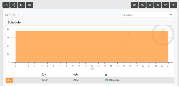
Click on the fourth black button from the top left to switch to code view:
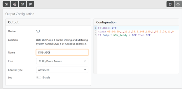
Add the off command after the tdata line. Leave everything else as is. And don’t forget to upload the new code.
The last task was to program an alert that notifies me when the saltwater is low. This just required adding “If Outlet NSW_Ready = OFF Then ON” to the email alarm virtual outlet.
That’s it. I’ve tested each input variable and condition I could think of and everything seems to work as planned.
I plan to track salinity drift with the DOS for a few weeks and then set up the dump bucket system. That will require a lot of additional programming, which I’ll post in a later update. Then I’ll compare how each system performs.
In terms of basic setup, the display tank (260 gallon) sits in a room against a wall to the garage so the sump and most support gear is in the garage right next to a hose bib (got lucky with that). So my RO/DI system, RO reservoir and salt water reservoir (each 80 gallons) are all right next to the sump. Here’s a picture of the basic layout:

I’ve already set up a basic auto top off system with a Tunze Osmolator, and installed a barrel-tender system (Buckeye Hydro) to refill the RO reservoir when it gets low without constantly cycling the RO/DI filter and magnifying the effects of TDS creep. The focus of this project was to program auto water changes in a smart way that pauses when salt water needs to be added and doesn’t resume until salinity is confirmed.
For the water change system, I have several goals/needs for the design. It needs to
- perform small daily water changes with little to no intervention;
- have the ability to perform on-demand larger water changes
- have high reliability
- have redundant failsafe features, including:
- won’t attempt an auto water change if my saltwater reservoir is running low
- won’t automatically reactivate water changes if the saltwater reservoir is refilled until I mix the salt and confirm salinity
- has multiple indicators to alert me when its time to mix a new batch of saltwater
In terms of hardware, the setup is pretty straightforward. In the picture above, the right reservoir is for RO/DI water. The RO unit feeds directly into that reservoir. The solenoid sitting right above the reservoir is part of the Buckeye Hydro barrel tender system that reduces TDS creep. I have a pump inside the reservoir that feeds the red PEX lines above. By turning the three ball valves on top, I can send that water either 1) through the wall into the display room to fill three dosing reservoirs in a cabinet next to the display tank; 2) into the saltwater reservoir; or 3) into the open tube in front, which I can use to pull a bucket of DI water or can connect to a longer hose to refill the ATO reservoir on my quarantine tank on the other side of the garage.
The left reservoir is the saltwater mixing reservoir. It has a couple powerheads that are always on. They are placed below the lowest level I let the reservoir drain to. There’s also a pump that feeds the PEX line coming out of the left side of the reservoir. I can use this to either add saltwater to the sump if I ever do a manual water change or can divert it to other destinations (like a bucket or hose to get it to my QT).
Ideally, I would have liked to elevate the saltwater reservoir and used a sloped bottom reservoir so I could periodically drain it entirely but this setup fit my space better. From time to time, the salt reservoir will accumulate nutrients or even algae and need to be thoroughly cleaned. I can manage it manually but the ability to fully drain it would be an improvement.
Sitting above the salt reservoir is the DOS that will do the water changes with tubes connected from the reservoir, to the sump, from the sump and to the drain. Setting up a DOS to do basic automatic water changes is relatively straightforward and there was a lot of good information out there on doing it. By far, the simplest approach is to just install it and run the Automatic Water Change Task in Apex Fusion. It walks you through the entire process pretty quickly and does the hard work. But this won’t provide the redundancy and other features I’m looking for. I wanted to try the Task Wizard so I started with this approach and found the Apex interface well thought out and easy to follow. Very quickly, it was set up to do automatic 4-gallon water changes each day.
For the additional features described above, a few more pieces of hardware and a fair amount of additional code is required. The hardware needed includes a breakout box, a momentary button to serve as an input to the BoB, two liquid level sensors (these can be the Apex optical sensors or float sensors), and two LED lights (I used the Adaptive Reef two-light module).
The logic of the system is as follows: When the saltwater reservoir is full of saltwater mixed to the proper salinity, all systems will be in “go” mode and the DOS will perform its water changes per whatever volume and timing is programmed in the Task Wizard. A green LED light mounted near the mixing station will be illuminated to show, at quick glance, that the system is working properly.

Two optical monitors (or floats) are installed in the saltwater reservoir – one low and one high. As the saltwater gets consumed and drops below the high sensor, nothing changes, but once it drops below the low sensor, the water changes are suspended, the green light turns off, a red light turns on and Apex sends me an alert that the saltwater reservoir is low.
The system remains in this suspended mode until I mix up new saltwater. I haven’t found it practical to automate the actual mixing of saltwater so this is my one manual step. In my case, that means opening a ball valve and activating a pump to transfer water from the RO reservoir to the saltwater reservoir, adding salt, waiting for it to mix, and fine tuning salinity. Once I confirm the saltwater is ready, I press a momentary button. The red light turns off; the green light turns on; the DOS resumes auto water changes.

I usually mix about 70 gallons of saltwater and the low sensor is around the 8 gallon mark, so at 4 gallons per day, this gets me about two and a half weeks.
For the programming, I created three virtual outlets. One is labeled NSW_Ready and acts as the final input to the hardware confirming all systems are go. One is labeled Hi_SW_VO (for high saltwater virtual outlet) and one is labeled Moment_VO (for momentary button virtual outlet).
The momentary button is wired to the breakout box and labeled NSW_OK. The LED lights are labeled GRN_LED and RED_LED. The Dos is labeled DOS_ADD and DOS_REMOVE as suggested by the task wizard. The optical level sensors are labeled NSW_Hi and NSW_Lo.
Here’s the code for each virtual outlet and the physical devices:
Virtual Outlets:
NSW_Ready
Set OFF
If Output Hi_SW_VO = ON Then ON
If Output Moment_VO = OFF Then OFF
If Output Moment_VO = ON Then ON
If NSW_Lo OPEN Then OFF
HI_SW_VO
Set OFF
If NSW_Hi OPEN Then OFF
If NSW_Hi CLOSED Then ON
Moment_VO
Set ON
If Output NSW_Ready = OFF Then OFF
If NSW_OK CLOSED Then ON
The effect of these programs is to allow multiple conditions to control when the NSW_Ready Virtual Outlet turns on and gives the system the all clear. The last line under the NSW_Ready code means that any time the low level sensor is dry, the outlet will turn off. For it to switch back on, it needs to check the HI_SW_VO outlet, which tracks the status of the high-level optical sensor. If that sensor is wet, the HI_SW_VO outlet will activate. The NSW_Ready outlet will read that and switch to on unless the next lines of code stop it. Then the NSW_Ready outlet checks the status of the momentary button. If I haven’t pushed it, which I do only when the saltwater is ready, the outlet stays off. If it have pushed it, it confirms the low optical sensor is wet before turning on.
The last line may seem unnecessary because, if the high sensor is wet the low must be as well. But it’s an important line because it is what causes the outlet to turn off when the reservoir is low.
The code for the Moment_VO outlet took a bit to figure out. Initially I had
Set OFF
If NSW_OK CLOSED Then ON
This had the effect of reactivating water changes and turning the LED green when I pressed it, but as soon as I released it, everything went back to off/red. Switching the set to ON fixed that and the line “If Output NSW_Ready = OFF Then OFF” provides an alternative way to turn this outlet off at the right time.
Physical Devices:
GRN_LED
If NSW_Ready = ON Then ON
If NSW_Ready = OFF Then OFF
RED_LED
If NSW_Ready = ON Then OFF
If NSW_Ready = OFF Then ON
The momentary button doesn’t need any code. It’s just an input.
For the DOS_ADD and DOS_REMOVE, I used the Auto Water Change Task to schedule 4 gallons of water per day. To suspend water changes when the saltwater reservoir is low, I added a line of code to each: If Output NSW_Ready = OFF Then OFF. To add this code, from the table view:

Click on the fourth black button from the top left to switch to code view:

Add the off command after the tdata line. Leave everything else as is. And don’t forget to upload the new code.
The last task was to program an alert that notifies me when the saltwater is low. This just required adding “If Outlet NSW_Ready = OFF Then ON” to the email alarm virtual outlet.
That’s it. I’ve tested each input variable and condition I could think of and everything seems to work as planned.
I plan to track salinity drift with the DOS for a few weeks and then set up the dump bucket system. That will require a lot of additional programming, which I’ll post in a later update. Then I’ll compare how each system performs.


