reef-pi :: An opensource reef tank controller based on Raspberry Pi.

OP
OP
Ranjib

Ranjib

7500 Club Member
View Badges
Joined
Apr 16, 2016
Messages
9,848
Reaction score
17,081
Location
Pleasant Hill, Concord
Rating - 0%
0   0   0
dashboard of my reefer 300xl, notice the temperature swing due to bad heater. It went long before I could get the time to investigate and address it.
1C67F0C0-6528-473E-81D9-65131EDA48CE.jpeg


and corresponding grafana dashboard, that has long term retention
reefer-300xl-tempswing.png


more i look at this graph, more i feel guilty :-( . Anyhow, no corals were lost, and now its fixed. When this problem initially started, i suspected the heater is not able to keep up .. since the temp control chart was showing heater is 100% time on. The internal thermister was turning off the heater, and that went undetected. Although, this was easily preventable, as the kasa hs300 provides current draw numbers and reef-pi can read this as analog sensor. Those number would make it abundantly clear that the 300w heater was barely drawing any current most of the time (when i manually checked, it was 1w ).
I hope i'll remember to add these learnings in the temperature controller guide (that not just temperature swing , but also the current draw of the heater can be used for early detection of failures)
 

Simonv92

Active Member
View Badges
Joined
Oct 21, 2014
Messages
145
Reaction score
105
Location
Italy
Rating - 0%
0   0   0
Hi All! I'm having trouble with an SHT31D reading, I was testing all on breadboard and everything works fine.
I've now moved the controller on a PCB and with the same lenght of cable I'm unable to read the data from my sensor.
I always have this error:

ph subsystem: Failed read probe:Sump TemperatureError:CRCs doesn't match: CRC from sensor (0xFF) != calculated CRC (0xA4)

I2C bus seems to works fine because I can detect the sensor at address 44 (68 on reef-pi) but I have comunication problems...
Also an LTC4311 didn't help me...
What can I try to do?
Thanks all!
 

zab34

Active Member
View Badges
Joined
Jan 23, 2012
Messages
335
Reaction score
71
Location
Orlando
Rating - 0%
0   0   0
This is awesome . You plan to opensource the design ? I’d love to build one
Unsure at the moment. I am sure there is some room for Improvement. Ideally I would have designed it to be more easily scalable for people’s various needs.
Right now I am going to let it run for the next month and see if I encounter any major issues.
 

robsworld78

Well-Known Member
View Badges
Joined
Feb 14, 2020
Messages
985
Reaction score
1,325
Location
Edmonton, Canada
Rating - 0%
0   0   0
Hi All! I'm having trouble with an SHT31D reading, I was testing all on breadboard and everything works fine.
I've now moved the controller on a PCB and with the same lenght of cable I'm unable to read the data from my sensor.
I always have this error:

ph subsystem: Failed read probe:Sump TemperatureError:CRCs doesn't match: CRC from sensor (0xFF) != calculated CRC (0xA4)

I2C bus seems to works fine because I can detect the sensor at address 44 (68 on reef-pi) but I have comunication problems...
Also an LTC4311 didn't help me...
What can I try to do?
Thanks all!
Some noise must be getting in the lines somewhere, maybe it's some equipment nearby, some LED drivers can emit noise. If you have one turned on see if it works better when its off or unplugged. You also might have to power cycle the Pi to get the I2C working again if it's hung up. How long is the cable? Try and keep it under a foot and if you can get shielded cable that will help. If you don't have for a quick fix try wrapping the cable in aluminum foil used for cooking. Even though you can read the address there could still be problems. Your best bet might be to get an ESP32, connect a DHT22 to it, you should be able to find example code on the web and then have the data sent to reef-pi using the new driver. DHT22 uses a digital pin so there will be no issues with long cables.
 

Jason Judd

Community Member
View Badges
Joined
Jul 8, 2018
Messages
30
Reaction score
16
Rating - 0%
0   0   0
Has anyone had issues with auto top off hanging? In the UI the toggle for on and off becomes unresponsive. And the actual Auto top off is not operating. I cleared up my database and rebuilt everything wondering if I had an issue in there. However with only the three basic Auto top offs that I'm using I'm still seeing the same issue.

ATO1: Standard Auto top off turning on a pump to pump in freshwater
ATO2: used on my protein skimmer overflow connected to a macro that turns off the protein skimmer and sends a text when the Overflow gets full
ATO3 (appears to be the culprit, all ATO stopped working in the same hour this teiggerd): used to detect high water on the main tank. When activated it temporarily shuts down part of the system and sends me a text. Typically the high water comes because of algae trapped on filter. Cycling the system often shifts the algae enough to get me going temporarily. It triggers once every couple of months and prevents an overflow spillage event.

Here's the image of the ATO, although it could be random that the ATOs stopped within an hour of this triggering. (I'll have to figure out uploading a photo a bit later today...)

Any thoughts?
 

Simonv92

Active Member
View Badges
Joined
Oct 21, 2014
Messages
145
Reaction score
105
Location
Italy
Rating - 0%
0   0   0
Some noise must be getting in the lines somewhere, maybe it's some equipment nearby, some LED drivers can emit noise. If you have one turned on see if it works better when its off or unplugged. You also might have to power cycle the Pi to get the I2C working again if it's hung up. How long is the cable? Try and keep it under a foot and if you can get shielded cable that will help. If you don't have for a quick fix try wrapping the cable in aluminum foil used for cooking. Even though you can read the address there could still be problems. Your best bet might be to get an ESP32, connect a DHT22 to it, you should be able to find example code on the web and then have the data sent to reef-pi using the new driver. DHT22 uses a digital pin so there will be no issues with long cables.
Hi Rob, thank you for your answer.
I’ve done some test:
I’m running a board with multiple PCA9507 as I2C extender; if I connect the sensor with 20cm of cable everything works fine.
If I run the full cable (around 2mt) to the same connector the sensor doesn’t work.

I’ve then tested the sensor attached to the outlet expansion board (which is connected to the cpu board by a bus extended by P82B96D): the PCA9685 that drives the output works without a problem, SHT31D connected to the same bus with 20cm of cable doesn’t work…

I was testing everything on a prototype board with very long cable (about 5 meters) and everything was working fine so I tought that with shorter cable I’ll not have any problem… could it be something related to the pullman-up resistor value? On my board I have 2.2K pull-up…
Let me know if tou have any idea, I’ll keep as last chance the use of the ESP32 only to read this sensor…
Thank you!
 

Sral

Valuable Member
View Badges
Joined
May 2, 2022
Messages
1,006
Reaction score
978
Location
Germany
Rating - 0%
0   0   0
Hi Rob, thank you for your answer.
I’ve done some test:
I’m running a board with multiple PCA9507 as I2C extender; if I connect the sensor with 20cm of cable everything works fine.
If I run the full cable (around 2mt) to the same connector the sensor doesn’t work.

I’ve then tested the sensor attached to the outlet expansion board (which is connected to the cpu board by a bus extended by P82B96D): the PCA9685 that drives the output works without a problem, SHT31D connected to the same bus with 20cm of cable doesn’t work…

I was testing everything on a prototype board with very long cable (about 5 meters) and everything was working fine so I tought that with shorter cable I’ll not have any problem… could it be something related to the pullman-up resistor value? On my board I have 2.2K pull-up…
Let me know if tou have any idea, I’ll keep as last chance the use of the ESP32 only to read this sensor…
Thank you!
2.2k actually sounds excessive, depending on the other components in the system that might also have internal pullups as well. I'm also unsure about the "multiple" PCA9507. I don't think you need multiple and they may in fact result in unwanted behavior. Adafruit was able to run an I2C line over 50m Ethernet cable with just ONE LTC4311.

I would recommend starting a dedicated thread and lay out the details of your setup: Power supplies, how they are connected to the PI, your I2C network and how that is powered/level shifted (if at all). That would help greatly in analysing the problem and helping you solve it.
 

robsworld78

Well-Known Member
View Badges
Joined
Feb 14, 2020
Messages
985
Reaction score
1,325
Location
Edmonton, Canada
Rating - 0%
0   0   0
Hi Rob, thank you for your answer.
I’ve done some test:
I’m running a board with multiple PCA9507 as I2C extender; if I connect the sensor with 20cm of cable everything works fine.
If I run the full cable (around 2mt) to the same connector the sensor doesn’t work.

I’ve then tested the sensor attached to the outlet expansion board (which is connected to the cpu board by a bus extended by P82B96D): the PCA9685 that drives the output works without a problem, SHT31D connected to the same bus with 20cm of cable doesn’t work…

I was testing everything on a prototype board with very long cable (about 5 meters) and everything was working fine so I tought that with shorter cable I’ll not have any problem… could it be something related to the pullman-up resistor value? On my board I have 2.2K pull-up…
Let me know if tou have any idea, I’ll keep as last chance the use of the ESP32 only to read this sensor…
Thank you!
No problem, and yeah something isn't right, the pca9507 is decent, I've used that part in the past and it definitely helps, 2 meters is doable. One thing to note which I forgot to mention is the Pi has 1.8k resistors already installed on the SDA and SCL pins so that may be enough. On my controller I rely on them before the 5v converter then I use 4.7k. With those 1.8k resistors and the 2.2.k you've installed you're down to 0.99k, then if the pca9507 has 2.2k now you have 3 pullups in parallel giving you 0.0022k which could definitely be a problem. As @Sral mentioned it's likely the extender and other devices on I2C have pullups so look for those and remove them if they have them.
 

Sral

Valuable Member
View Badges
Joined
May 2, 2022
Messages
1,006
Reaction score
978
Location
Germany
Rating - 0%
0   0   0
No problem, and yeah something isn't right, the pca9507 is decent, I've used that part in the past and it definitely helps, 2 meters is doable. One thing to note which I forgot to mention is the Pi has 1.8k resistors already installed on the SDA and SCL pins so that may be enough. On my controller I rely on them before the 5v converter then I use 4.7k. With those 1.8k resistors and the 2.2.k you've installed you're down to 0.99k, then if the pca9507 has 2.2k now you have 3 pullups in parallel giving you 0.0022k which could definitely be a problem. As @Sral mentioned it's likely the extender and other devices on I2C have pullups so look for those and remove them if they have them.
My thinking as well, the 5V Converter might also have another 10k on both sides as well.
My Setup does absolutely fine So far using only internal pull-ups on:
3.3V line:
Pi Zero
Adafruit ISO1540 (isolation and level shifting)

5V line:
Adafruit ISO1540
Adafruit LTC4311 (dynamic pull-up)
RTC module
Adafruit SCD30 Module ( after 1m of shielded USB cable)
 

Simonv92

Active Member
View Badges
Joined
Oct 21, 2014
Messages
145
Reaction score
105
Location
Italy
Rating - 0%
0   0   0
Thank you for all of the answers!
My setup is this one:
Custom PCB with 2.2K Pull-up on 3.3V I2C Bus Line.
On this bus I have:
- 1x P82B96D to extend bus to output board (works fine)
- 1x DS3231 RTC (seems to works fine)
- 4x PCA9507 to have 4 dedicated I2C output at 5V - each outup have his own 2.2K pull up
- 1x ADS1115 ADC (works fine)

Now I've removed the main 2.2K resistor (since raspberry has his own) and I'm trying to connect the SHT31D directly to the 3.3V bus and power.
I'm doing a reading every 30 sec and I'm having some numbers.. at some times the reading is 0 but it's a step forward.
Now I'll try again with PCA9507 as level converter...
@Sral do you have any photo of your setup?
thank you!
 
Last edited:

Sral

Valuable Member
View Badges
Joined
May 2, 2022
Messages
1,006
Reaction score
978
Location
Germany
Rating - 0%
0   0   0
Have a look on page 6 of the PCA9507's datasheet. It specifies typicall pull-up values of 10k and gives some formulas on what minimum and maximum Pull-Ups to use. They do for example mention that the minimum Pull-Up Resistor value depends on the maximum Pull-down current of your device(s).
The P82B96's datasheet for example mentions a maximum output sink capability on I2C bus of 5.5mA, which equates to a minimum total pull-up resistance to 5V of 0.9k.
The SHT31D's datasheet mentions a sink current of 3mA, at 5V that euqates to a minimum total pull-up value of 1.37k . That's already pretty close to your 2.2k
The DS3231's datasheet mentions the same conditions, 1 to 3mA.

I would therefore caution against such strong pull-ups.

@robsworld78 1.8k on a PI sounds way too little resistance. I have looked it up: here under "voltage specifications" it mentions a pull up between 50 to 65k. That sounds more reasonable.


@Simonv92 You can find a few pictures of my setup in my build thread, like this post for example. I have made a kind of switchboard for the I2C line, which you can see here. The switchboard is the big block of 2x8 female headers, made up of 4 blocks of interconnected 2x2 female headers, one block for each of VCC, GND, SCL and SDA. It's simply there to power the 5V side of my I2C network and provide connection to all 4 "devices", e.g. one line in from the level shifter, one line out to the USB sockets and one line each to the LTC4311 dynamic pull-up and RTC module.
If you scroll a bit down to this post you can see the SCD30 Air Quality sensor that I have connected via a 1m shielded USB cable using USB-A sockets. The only strange thing is that I can't get a connection to the BMP280 air pressure sensor, that's connected identically next to the SCD30.
Downside to this is the ridiculuosly long power line that has way to many connectors with contact resistance, so I'll probably have to be carefull with current hungry devices :grinning-face-with-sweat:
 
Last edited:

Simonv92

Active Member
View Badges
Joined
Oct 21, 2014
Messages
145
Reaction score
105
Location
Italy
Rating - 0%
0   0   0
Thank you very much @Sral, I've already seen the PCA9507 datasheet and I've choosen 2.2K based on the informations right there...
All of the devices connected before the PCA9507 works fine (DS3231, P82B96). I've now connected a Ph board to the PCA9597 with 20cm of cable and it works fine (the same thing does SHT31D with 20cm of cable).
Now I'm able to run SHT31D with long cable only attaching it directly to the 3.3V bus which sounds a bit strange, since the PCA should improve the signal quality over long distances...
I don't know what to do... maybe I can try a setup like yours, with a ISO1540 as level shifter from 3.3 to 5V and a LTC4311 to improve signal quality (which I already have but in my setup does nothing...)
What do you think?
 

Sral

Valuable Member
View Badges
Joined
May 2, 2022
Messages
1,006
Reaction score
978
Location
Germany
Rating - 0%
0   0   0
Thank you very much @Sral, I've already seen the PCA9507 datasheet and I've choosen 2.2K based on the informations right there...
All of the devices connected before the PCA9507 works fine (DS3231, P82B96). I've now connected a Ph board to the PCA9597 with 20cm of cable and it works fine (the same thing does SHT31D with 20cm of cable).
Now I'm able to run SHT31D with long cable only attaching it directly to the 3.3V bus which sounds a bit strange, since the PCA should improve the signal quality over long distances...
I don't know what to do... maybe I can try a setup like yours, with a ISO1540 as level shifter from 3.3 to 5V and a LTC4311 to improve signal quality (which I already have but in my setup does nothing...)
What do you think?
Hmm sounds like the pull up might still be the problem. 3.3V also means less current to sink to properly pull down the signal line, both through the pull-up and the lower charge on the cable capacitance.

I would therefore recommend trying a larger pull-up resistor.

how did you arrive at the 2.2k value ?
 

robsworld78

Well-Known Member
View Badges
Joined
Feb 14, 2020
Messages
985
Reaction score
1,325
Location
Edmonton, Canada
Rating - 0%
0   0   0
@robsworld78 1.8k on a PI sounds way too little resistance. I have looked it up: here under "voltage specifications" it mentions a pull up between 50 to 65k. That sounds more reasonable.
50k to 65k sounds a little excessive. :) Never seen anything on I2C bus that high. I'm wondering if those values are for the other GPIO's. I get 1.8k from here and I've seen other specs saying the same.


Sral

Valuable Member
View Badges
Joined
May 2, 2022
Messages
1,006
Reaction score
978
Location
Germany
Rating - 0%
0   0   0
50k to 65k sounds a little excessive. :) Never seen anything on I2C bus that high. I'm wondering if those values are for the other GPIO's. I get 1.8k from here and I've seen other specs saying the same.

Interesting. Well, 50-65k are not realy excessive, they provide some kind of pull-up, but won't overpower devices with very little pull-down capability, so it sounds like a compromise between having at leat A pull-up, while also having compatibility with weak devices. Maybe those 50-60k are the on-chip resistors and 1.8k are external on the board, that could make sense. Something to learn every day !

Thank you very much @Sral, I've already seen the PCA9507 datasheet and I've choosen 2.2K based on the informations right there...
All of the devices connected before the PCA9507 works fine (DS3231, P82B96). I've now connected a Ph board to the PCA9597 with 20cm of cable and it works fine (the same thing does SHT31D with 20cm of cable).
Now I'm able to run SHT31D with long cable only attaching it directly to the 3.3V bus which sounds a bit strange, since the PCA should improve the signal quality over long distances...
I don't know what to do... maybe I can try a setup like yours, with a ISO1540 as level shifter from 3.3 to 5V and a LTC4311 to improve signal quality (which I already have but in my setup does nothing...)
What do you think?
Another thing: could you provide a picture or circuit diagram of the important VCC, GND, SDA, SCL lines from the PI to the PCA9507 ? I just read in the PCA9507's datasheet (first page), that you can't combine several PCA9507's A sides together, because the voltage offsets would interfere with the I2C bus' operation.
Maybe that's making communication beyond the PCA9507 impossible, because as soon as the SHT31D pulls it's side low, the other side might get stuck, since none of the four PCA9507 knows anymore where the communication is comming from and keeps pulling the lines "Low", e.g below 0.5V.
 
Last edited:

Simonv92

Active Member
View Badges
Joined
Oct 21, 2014
Messages
145
Reaction score
105
Location
Italy
Rating - 0%
0   0   0
Interesting. Well, 50-65k are not realy excessive, they provide some kind of pull-up, but won't overpower devices with very little pull-down capability, so it sounds like a compromise between having at leat A pull-up, while also having compatibility with weak devices. Maybe those 50-60k are the on-chip resistors and 1.8k are external on the board, that could make sense. Something to learn every day !


Another thing: could you provide a picture or circuit diagram of the important VCC, GND, SDA, SCL lines from the PI to the PCA9507 ? I just read in the PCA9507's datasheet (first page), that you can't combine several PCA9507's A sides together, because the voltage offsets would interfere with the I2C bus' operation.
Maybe that's making communication beyond the PCA9507 impossible, because as soon as the SHT31D pulls it's side low, the other side might get stuck, since none of the four PCA9507 knows anymore where the communication is comming from and keeps pulling the lines "Low", e.g below 0.5V.
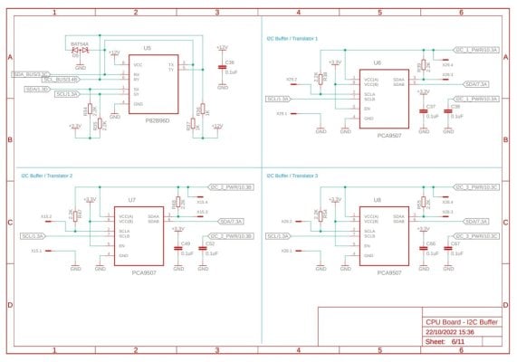
Here is the schematic of the Bus expander (the 4th channel is missing but it's the same)
The main bus is connected on Port B on every expander.
Now I'm running the SHT31D directly on the 3.3V bus without any IC between and it seems to work. I don't understand why the PCA are blocking the signal...
If in this way it works I can remove all of the 9507 and add an ISO1540 as voltage converter and run everything without any bus expander...
 

Attachments

  • I2C Buffer.jpg
    I2C Buffer.jpg
    114.8 KB · Views: 62

Simonv92

Active Member
View Badges
Joined
Oct 21, 2014
Messages
145
Reaction score
105
Location
Italy
Rating - 0%
0   0   0
Another question, How do I calibrate a single point calibration probe such as ORP?
If I set 225mV for both mid value and second point I always have 225 reading... I'm missing something :downcast-face-with-sweat:
 

Sral

Valuable Member
View Badges
Joined
May 2, 2022
Messages
1,006
Reaction score
978
Location
Germany
Rating - 0%
0   0   0
Here is the schematic of the Bus expander (the 4th channel is missing but it's the same)
The main bus is connected on Port B on every expander.
Now I'm running the SHT31D directly on the 3.3V bus without any IC between and it seems to work. I don't understand why the PCA are blocking the signal...
If in this way it works I can remove all of the 9507 and add an ISO1540 as voltage converter and run everything without any bus expander...
I realized something, that I didn’t notice before: you have several components that provide I2C extension. Maybe I should have read more carefully or you could have stressed this a bit more.
Could you provide a sketch of your I2C network, e.g. which components translate this network from and to which components ?

I’m worried that the P82B96 might not play well with the PCA9507. It says something like this in the datasheet:
„slightly different logic low-voltage levels are used at Sx/Sy to avoid latching of this buffer. A standard I2C low applied at the Rx/Ry of a P82B96 is propagated to Sx/Sy as a buffered low with a slightly higher voltage level.“
On the PCA9507:
„The static level offset design of the port B I/O drivers prevent them from being connected to another device that has rise time accelerator“

So if both use Offsets and accelerators, they might latch up. You can test this by connecting the SHT31D in the original not working condition and measuring the DC voltage on the lines. If they are too low (e.g. below 1V) it probably means that they are latched up.
Another fault might be, that the voltage offset of LOW state on the PCA9507‘s B-side might not be properly recognized by the P82B96, or vice versa.
 
Last edited:

Simonv92

Active Member
View Badges
Joined
Oct 21, 2014
Messages
145
Reaction score
105
Location
Italy
Rating - 0%
0   0   0
I realized something, that I didn’t notice before: you have several components that provide I2C extension. Maybe I should have read more carefully or you could have stressed this a bit more.
Could you provide a sketch of your I2C network, e.g. which components translate this network from and to which components ?

I’m worried that the P82B96 might not play well with the PCA9507. It says something like this in the datasheet:
„slightly different logic low-voltage levels are used at Sx/Sy to avoid latching of this buffer. A standard I2C low applied at the Rx/Ry of a P82B96 is propagated to Sx/Sy as a buffered low with a slightly higher voltage level.“
On the PCA9507:
„The static level offset design of the port B I/O drivers prevent them from being connected to another device that has rise time accelerator“

So if both use Offsets and accelerators, they might latch up. You can test this by connecting the SHT31D in the original not working condition and measuring the DC voltage on the lines. If they are too low (e.g. below 1V) it probably means that they are latched up.
Another fault might be, that the voltage offset of LOW state on the PCA9507‘s B-side might not be properly recognized by the P82B96, or vice versa.
Thank you @Sral for all your help!
I2C diagram is this one:

Raspberry Pi Zero W 2 -> 3.3V Bus
3.3V Bus -> P82B96 to expansions board (equipped with another P82B96 to decode bus)
3.3V Bus -> DS3231 RTC
3.3V Bus -> ADS1115 ADC
3.3V Bus -> PCA9507 -> 5.0V Bus 1 to external devices -> 4 way terminal block
3.3V Bus -> PCA9507 -> 5.0V Bus 2 to external devices -> 4 way terminal block
3.3V Bus -> PCA9507 -> 5.0V Bus 3 to external devices -> 4 way terminal block
3.3V Bus -> PCA9507 -> 5.0V Bus 4 to external devices -> 4 way terminal block

Let me know if it's clear otherwise I'll draw it graphically..
 

Sral

Valuable Member
View Badges
Joined
May 2, 2022
Messages
1,006
Reaction score
978
Location
Germany
Rating - 0%
0   0   0
Thank you @Sral for all your help!
I2C diagram is this one:

Raspberry Pi Zero W 2 -> 3.3V Bus
3.3V Bus -> P82B96 to expansions board (equipped with another P82B96 to decode bus)
3.3V Bus -> DS3231 RTC
3.3V Bus -> ADS1115 ADC
3.3V Bus -> PCA9507 -> 5.0V Bus 1 to external devices -> 4 way terminal block
3.3V Bus -> PCA9507 -> 5.0V Bus 2 to external devices -> 4 way terminal block
3.3V Bus -> PCA9507 -> 5.0V Bus 3 to external devices -> 4 way terminal block
3.3V Bus -> PCA9507 -> 5.0V Bus 4 to external devices -> 4 way terminal block

Let me know if it's clear otherwise I'll draw it graphically..
That's clear enough, thanks.

Hmmmm, the datasheets are not clear enough for me to judge the compatibility of the P82B96 and PCA9507 in your situation with certainty. Maybe you can test it out, e.g. connect the SHT31D to the PC9507 (test several, in case the one used is broken) , remove or deactivate the P82B96 from the network and see if the connection works then.

Another thing I noticed on the PCA9507: the datasheet only mentions standard topographies of multiple A-Port together in a star-topography, or A and B ports in series. So maybe they don't play well with each other, when you connect multiple B-ports to each other ? To test that you would of course have to remove or deactivate 3 of the 4 PCA9507's and then connect the SHT31D to the remaining one.

I hope that is even possible for you and you can find a solution.
 
Back
Top