Matt Carden

Valuable Member
View Badges
Joined
Apr 13, 2018
Messages
1,647
Reaction score
4,086
Location
Detroit Metro
Rating - 0%
0   0   0
I set up my 1st intended reef tank in November of '18. I decided to go with a 150 gallon because water parameters are supposed to be more stable and I love fish too so I could have a wider selection with a 5' tank.

I realized shortly after setting up this tank that my attempt at a budget build was fraught with issues. I had an ATO running RODI straight into sump without reservoir. The solenoid wouldn't consistently close or open so sometimes I was left with a flood and sometimes I was left with low water level. I had my lights controlled at full intensity with a plug in dial timer. I didn't set up any dosers either when started up. I found out how much of a pain it is to do water changes without a water mixing/changing station. Last but not least I had a major issue with the way i set up the wire routing. I was shocked, I had a powerhead power supply fall in the tank (thankfully unplugged), and I found out how corroded plugs can get being around warm saltwater.

Fast forward about 6 months and I had to move from Georgia to Michigan. During the move I chipped the top edge of the side of the tank. This presented an opportunity to rebuild the right way. I have a build thread for this rebuild here: https://www.reef2reef.com/threads/matts-sca-150-repair-and-redesign.659967/

I've been contemplating the need for a controller since I started buying the initial equipment. I looked into the 2 main controllers that were available at the time. They were both fairly expensive and I thought no way I'm spending that much to have a controller. As my plans for a controller evolved it became evident that the basic $900 controller wasn't enough to control what I wanted and I would have to buy extension. Reef-Pi came across my radar while exploring all there is to learn on Reef2Reef. When i first started looking at Reef-Pi there wasn't any plug and play circuitry being offered but now there are at least 2 to chose from. I decided to use the @Michael Lane Hat for the majority of my circuitry.

What I plan for my controller to control:
4 powerheads for on/off relay control
1 return pump for on/off relay control
2 light channels sunrise/sunset
Moonlight phases if that becomes part of a future release.
3 Fuge lights on/off
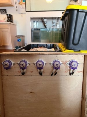
5 Kamoer doser pumps
5 level sensors for dosing containers
2 ground probes one in each tank
ATO pump controlled by 2 mechanical level sensors
Air pump for on/off relay control
1 mechanical level sensor for Phyto
2 Temperature sensors
2 Finnex digital heaters for on/off
Ph probe
3 solenoids RODI into mixing station
4 level sensors for mixing station hi/lo
5 solenoids for AWC
1 pump mixing station

My knowledge of electronics is good enough to connect wires and some soldering. I tried through board soldering with a basic iron with probably 80% good joints. I picked up a soldering station which is much easier to use. This station should bring me up to 98% when I will inevitably have to build some circuitry.
 
Last edited:
OP
OP
Matt Carden

Matt Carden

Valuable Member
View Badges
Joined
Apr 13, 2018
Messages
1,647
Reaction score
4,086
Location
Detroit Metro
Rating - 0%
0   0   0
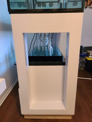
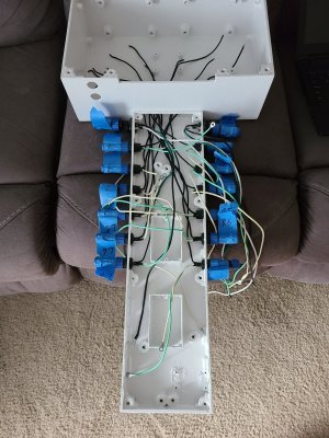
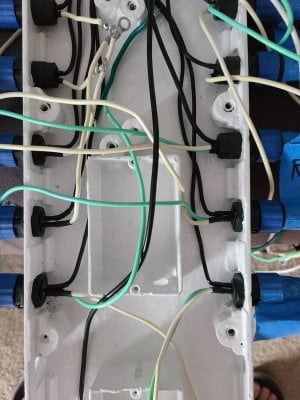
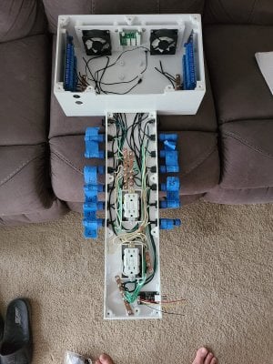
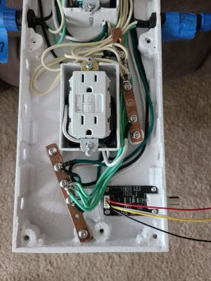
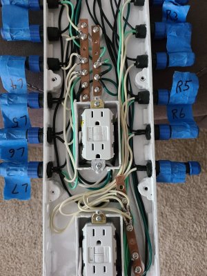
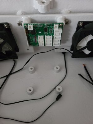
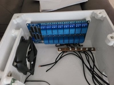
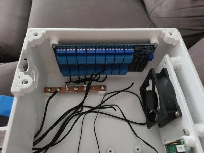
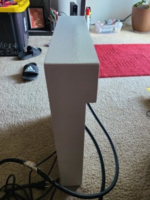
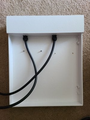
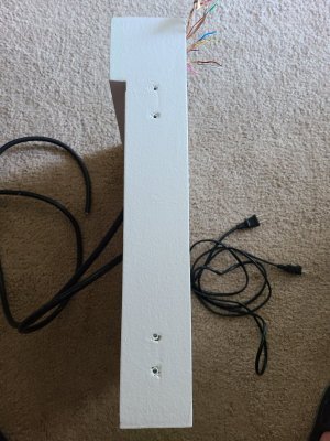
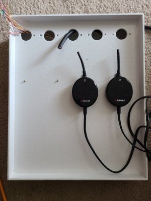
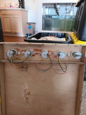
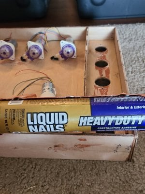
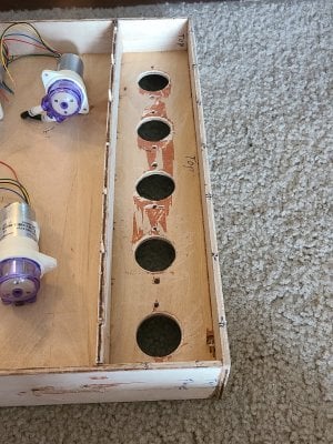
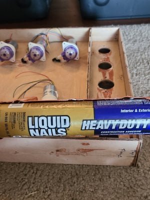
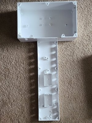
I built a custom controller box and power strip out of .20" thick plywood/underlayment/Lauan. The controller box is built to fit between the corner posts of the stand on what will be the front side in a Pennisula configuration. I decided to use plastic IP67 plugs for pretty much every connection to reduce corrosion of the connectors. The only reason there are standard wall plugs in my controller box is because of the GFCI. I am splitting the power into 2 GFCI in hopes that if one pops there will be flow or heat from the other circuit in each tank. I have most of the 110v wiring complete in the control box.

15965857617965210930082154997595.jpg 15965868590583538413921756046248.jpg 15965871485042560223168864077761.jpg
 
Last edited:
OP
OP
Matt Carden

Matt Carden

Valuable Member
View Badges
Joined
Apr 13, 2018
Messages
1,647
Reaction score
4,086
Location
Detroit Metro
Rating - 0%
0   0   0
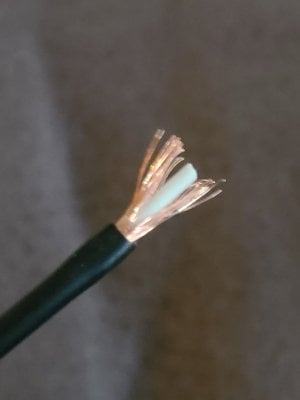
I started looking at wiring between the ML hat and the Ph adapter and the temp sensors which created my first question. How to prevent signal interferences on an I2C over 30" of wire? Also the temp sensor plugs are 24" from the hat. I have this wire:
15965857617965210930082154997595.jpg

Could I run a separate run of the above for the SDA and one for the SCL with the shields of each grounded at one end only? I should also be able to run this same wire for the signal wire of the temp probes?

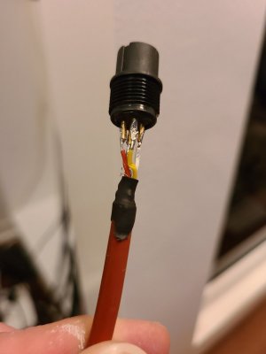
Additionally I have a question about wire identification on these temp probes?
15965868590583538413921756046248.jpg

There is a bare wire in the background which I assume is the cable shield. @Ranjib this doesn't match up with the colors in your guide. The closest I came up with is it's a Japanese standard. Would I need to have all three wires shielded or just the signal wire?
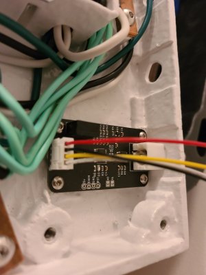
15965871485042560223168864077761.jpg

@Micheal lane can you identify what wires these are to connect to your hat?
 
Last edited:
Michael Lane

Well-Known Member
View Badges
Joined
Aug 11, 2018
Messages
677
Reaction score
1,123
Rating - 0%
0   0   0
That first wire looks like coax. 30" is kind of a long way for i2c. Running each signal through separate shielded cables can work as you've described, but a single multi conductor shielded cable would probably be better. Another way to improve i2c reliability can be to slow the bus down.

What is the temperature probe? Can you post a link to the product?
 
OP
OP
Matt Carden

Matt Carden

Valuable Member
View Badges
Joined
Apr 13, 2018
Messages
1,647
Reaction score
4,086
Location
Detroit Metro
Rating - 0%
0   0   0
That first wire looks like coax. 30" is kind of a long way for i2c. Running each signal through separate shielded cables can work as you've described, but a single multi conductor shielded cable would probably be better. Another way to improve i2c reliability can be to slow the bus down.

What is the temperature probe? Can you post a link to the product?
Would the multi- conductor need to be individually shielded? Would a cat5e work?

I can't find the receipt of purchase or even where I purchased it.
 
OP
OP
Matt Carden

Matt Carden

Valuable Member
View Badges
Joined
Apr 13, 2018
Messages
1,647
Reaction score
4,086
Location
Detroit Metro
Rating - 0%
0   0   0
I tried to use a USB cable for my Ph interface cable but when I tried to install it in the control box the wire broke. I decided I didn't want to deal with broken wires or interference so I picked up some 18ga individually shielded industrial instrumentation cable https://www.wireandcableyourway.com...ray-cable-individual-overall-shield-600v.html .
20200906_114830.jpg
20200906_114218.jpg
20200906_112617.jpg
20200906_112535.jpg
20200906_112406.jpg
20200906_112229.jpg
20200906_112200.jpg

I also used this cable for the temperature sensor extension from
 
OP
OP
Matt Carden

Matt Carden

Valuable Member
View Badges
Joined
Apr 13, 2018
Messages
1,647
Reaction score
4,086
Location
Detroit Metro
Rating - 0%
0   0   0
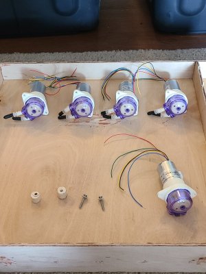
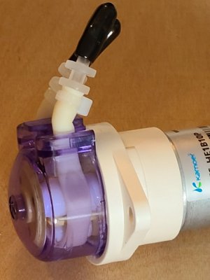
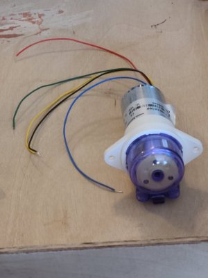
I need to figure out these Kamoer dosing pumps i purchased from Alibaba. I believe they are brushless motors with internal controllers. There are 5 wires coming out:
20200604_170825.jpg

I searched online for days trying to find anything referencing a 5 wire brushless motor. I could only find 1 reference:

What I have come up with is that if I connect 12+ to pin 5 and grd to pin 2 no power will run through the motor until I activate the PWM signal from the hat to pin 1. It seems like if I don't connect pins 3 or 4 it should operate in a forward direction.
 

Mikeneedsahobby

Well-Known Member
View Badges
Joined
Sep 16, 2018
Messages
516
Reaction score
922
Rating - 0%
0   0   0
Looks like you got the wiring for the doser provided in the main reef pi thread. I am curious how this works out. I am disappointed in the jebao dp4 doser I have. I was looking for a better doser head I could interface to reef pi. Do you have a link to where you bought those?
 
OP
OP
Matt Carden

Matt Carden

Valuable Member
View Badges
Joined
Apr 13, 2018
Messages
1,647
Reaction score
4,086
Location
Detroit Metro
Rating - 0%
0   0   0
This documentation was posted on the main reef-pi thread by @theatrus :
Kamoerbrushlesswiringdiagram.png

This verifies what I found online so I will be using this to hook up these dosers.
 
OP
OP
Matt Carden

Matt Carden

Valuable Member
View Badges
Joined
Apr 13, 2018
Messages
1,647
Reaction score
4,086
Location
Detroit Metro
Rating - 0%
0   0   0
I need help figuring out where to hook up wires on an ML hat. In the attached picture the attachments I'm having trouble with are the " V+" , "NC" , and "5V ? Also the 12v+ power connector is where the power supply power out goes right?
Screenshot_20201031-131906_Chrome.jpg

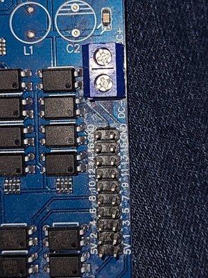
Here us the relay board the ML hat will be connecting.
20201031_133010.jpg

Then on the left side of the board there is a connector for 5v power. Is this 5v out?
Screenshot_20201031-132702_Chrome.jpg
 

Mikeneedsahobby

Well-Known Member
View Badges
Joined
Sep 16, 2018
Messages
516
Reaction score
922
Rating - 0%
0   0   0
J13 5v is 5v in
5v on right side is 5v out if you need it.
nc is a dead pin
V+ Is 12v out
The 12v connector on right is 12v in

the 12v circuit is for the uln2803 only. You can put 5v in instead of 12 and then the v+ is 5v
 
OP
OP
Matt Carden

Matt Carden

Valuable Member
View Badges
Joined
Apr 13, 2018
Messages
1,647
Reaction score
4,086
Location
Detroit Metro
Rating - 0%
0   0   0
So the description of this board on Tindie mentions backpowering the raspberry pi. Which connector is that? I assumed it was the j5.
 
OP
OP
Matt Carden

Matt Carden

Valuable Member
View Badges
Joined
Apr 13, 2018
Messages
1,647
Reaction score
4,086
Location
Detroit Metro
Rating - 0%
0   0   0
And what voltage do you think the DC+ would be? This relay is a 5v relay. There is a location for 5v which i assume is in or out? DC- would be grd.

20201031_133010.jpg
 

Mikeneedsahobby

Well-Known Member
View Badges
Joined
Sep 16, 2018
Messages
516
Reaction score
922
Rating - 0%
0   0   0
And what voltage do you think the DC+ would be? This relay is a 5v relay. There is a location for 5v which i assume is in or out? DC- would be grd.

20201031_133010.jpg
I’m not sure what this board is. I’m guessing 5v and gnd on the line of double pins is the control side power in. This would come from the hat.
I’m thinking dc- and dc+ is the high voltage/amp side power in. This would come straight from a power supply. (If I’m guessing right. )
 
OP
OP
Matt Carden

Matt Carden

Valuable Member
View Badges
Joined
Apr 13, 2018
Messages
1,647
Reaction score
4,086
Location
Detroit Metro
Rating - 0%
0   0   0
I’m not sure what this board is. I’m guessing 5v and gnd on the line of double pins is the control side power in. This would come from the hat.
I’m thinking dc- and dc+ is the high voltage/amp side power in. This would come straight from a power supply. (If I’m guessing right. )
Thank you for you help. I hope nothing fries when I power up
 
Back
Top