Navigation
Install the app
How to install the app on iOS
Follow along with the video below to see how to install our site as a web app on your home screen.
Note: This feature may not be available in some browsers.
More options
You are using an out of date browser. It may not display this or other websites correctly.
You should upgrade or use an alternative browser.
You should upgrade or use an alternative browser.
Unidentifiable DIY Sump design
- Thread starter randadesfal
- Start date
-
- Tags
- diy help sump used equipment
- Tagged users None
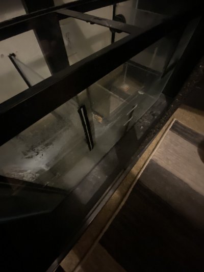
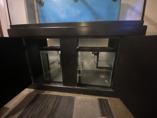
I can't even understand where the baffles are based on those pictures. A lot easier for people to see and help with a clear picture from the top and the front without the cross brace of your stand in the way.
it would be easier if i could remove the sump from the stand buuuut it would seem the stand was built around the sump, let me pull it out and take a picture from the backside that should helpI can't even understand where the baffles are based on those pictures. A lot easier for people to see and help with a clear picture from the top and the front without the cross brace of your stand in the way.
it would be easier if i could remove the sump from the stand buuuut it would seem the stand was built around the sump, let me pull it out and take a picture from the backside that should help
I just want to understand the floating box lolI can't even understand where the baffles are based on those pictures. A lot easier for people to see and help with a clear picture from the top and the front without the cross brace of your stand in the way.
What does the text on the labels say? in your final image, it looks like the drain section is all the way on the right, followed by a fixed height skimmer/heater/refugium section, followed by the return pump section on the bottom left. Perhaps the top left section is for a separate drain/refugium area.
minimum water level and maximum water levelWhat does the text on the labels say? in your final image, it looks like the drain section is all the way on the right, followed by a fixed height skimmer/heater/refugium section, followed by the return pump section on the bottom left. Perhaps the top left section is for a separate drain/refugium area.
My guess would be that the floating box was some kind of raised refugium. Water entered the box through one bulkhead, then exited out the other through an 90-degree drain pipe down into the chamber beneath it.
But, like I said, really just a guess.
But, like I said, really just a guess.
OHHH THAT WOULD MAKE SENSEMy guess would be that the floating box was some kind of raised refugium. Water entered the box through one bulkhead, then exited out the other through an 90-degree drain pipe down into the chamber beneath it.
But, like I said, really just a guess.
This looks a little similar to one I built a few years ago.
Yes the floating box was either a refugium or a tank to segregate new fish or fish that needed to be seperated for one reason or another.
I used mine for a fuge. Just bare in mind you will hear the over flow trickle back into the sump. So flow will need to be rather minimal.
As for baffle number 2 from the right it's not doing anything there. Id remove that and install it back just infront of the return baffle to create some sort of bubble trap. Or better still remove baffle 2 and 3 and replace them in better locations as the return chamber is going to run pretty low.
(looks like this was designed for the skimmer hight)
You should be able to get glass cut pretty easy. But if not you can use 5mm arcrylic which you can cut with a jig saw, silicone that into place and your OK. As there is equal pressure on both side the silicone will be fine in this application.
You also have the option to keep baffle 2, fix a sheet of arcrylic between the top of baffle 1 and 2 about 2cm below the top, pre cut to accept filter socks. Then increase the hight of baffle 3 to control water height and noise, and add another baffle to creat a bubble trap just before the return baffle
You could also remove baffle 1 and 2. move 2 to create a bubble trap, increase hight of return baffle then add some sort of roller mat.
The options are unlimited really. The sump is a good size.


