Repairing EB832 AquaBus Power Issues or Why Head Unit Reboots Again

Neptune

DrZoidburg

Valuable Member
Review score
+0 /0 /-0
View Badges
Joined
May 22, 2021
Messages
1,577
Reaction score
1,073
Review score
+0 /0 /-0
Location
Near Lake George
Rating - 0%
0   0   0
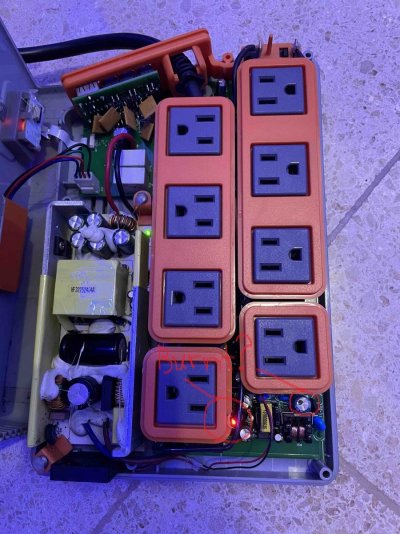
This is what I see. @Rimsky I circled things that did not look right.
 

Attachments

  • eb.jpg
    eb.jpg
    307.6 KB · Views: 59
www.dinkinsaquaticgardens.com

Rimsky

Active Member
Review score
+0 /0 /-0
View Badges
Joined
Jul 24, 2016
Messages
133
Reaction score
30
Review score
+0 /0 /-0
Rating - 0%
0   0   0
Hi @DrZoidburg.
the burned plastic was caused by myself with my soldering iron. My bad.

the black marking on the capacitor came like that. It seems just like a marking made with a permanent marker. Both new PSUs that I ordered came with that marking. I’m getting 12v dc out of the PSU. Can it still be bad? Is there a way I can test it other than the 12v dc output pins?

thanks a lot!
 
OP
OP
_AV

_AV

Well-Known Member
Review score
+0 /0 /-0
View Badges
Joined
Oct 3, 2019
Messages
591
Reaction score
589
Review score
+0 /0 /-0
Rating - 0%
0   0   0
If the 12v PSU can't power the relays, its red LED usually flickers or goes dark when under load. Since you completely replaced the PSU, which is not my recommended approach, I'd make sure that the voltage it produces is actually 12v and not 5v.
 
AquaCave Logo Banner

Rimsky

Active Member
Review score
+0 /0 /-0
View Badges
Joined
Jul 24, 2016
Messages
133
Reaction score
30
Review score
+0 /0 /-0
Rating - 0%
0   0   0
Dear @_AV, the led on the 12v PSU is solid red and my multimeter reads 12v DC on the output pins. When I change the status of any outlet via Apex Fusion, the status lights on EB832 change, but there is no relay sound at all, not even a subtle sound. I will check everything again today, but really don't know what else to look for.
 
OP
OP
_AV

_AV

Well-Known Member
Review score
+0 /0 /-0
View Badges
Joined
Oct 3, 2019
Messages
591
Reaction score
589
Review score
+0 /0 /-0
Rating - 0%
0   0   0
Have you tested the 24v outlets yet?

Also, the 12v PSU provides power to each relay to toggle it when the controller tells it to. With the outlet in ON state in fusion, trace the 12v power from the PSU all the way to the relay coil pin and make sure it's actually there. Which is unlikely. In which case, find out how far it goes from the PSU and why it stops where it does.
 

Rimsky

Active Member
Review score
+0 /0 /-0
View Badges
Joined
Jul 24, 2016
Messages
133
Reaction score
30
Review score
+0 /0 /-0
Rating - 0%
0   0   0
I did some investigation with my limited skills. The 1Link 24VDC outlets work. The relays click and there is 24V DC.

The 120VAC outlets still don't work. I can measure 12V on some of the relay pins, well, actually 11.26 VDC, not 12V. On those pins I can measure 11.24 VDC all the time, regardless of the outlet ON/OFF status.

The fan does not move. I'm not getting any voltage there.
 

DrZoidburg

Valuable Member
Review score
+0 /0 /-0
View Badges
Joined
May 22, 2021
Messages
1,577
Reaction score
1,073
Review score
+0 /0 /-0
Location
Near Lake George
Rating - 0%
0   0   0
Have you checked under side of the board one video mentions some of the resistors burning out in other cases. Similar to yours with fan not working his was power supply also. Good idea to check triacs under the outlets if it is like older classic models. Could unplug the fan from pins and test pins with meter to rule out broken fan.
 
OP
OP
_AV

_AV

Well-Known Member
Review score
+0 /0 /-0
View Badges
Joined
Oct 3, 2019
Messages
591
Reaction score
589
Review score
+0 /0 /-0
Rating - 0%
0   0   0
I did some investigation with my limited skills. The 1Link 24VDC outlets work. The relays click and there is 24V DC.

The 120VAC outlets still don't work. I can measure 12V on some of the relay pins, well, actually 11.26 VDC, not 12V. On those pins I can measure 11.24 VDC all the time, regardless of the outlet ON/OFF status.

The fan does not move. I'm not getting any voltage there.
Just making sure you tested the aux 24v outlets, those with only 2 pins and not 4. 1Link outlets with 4 pins always have 24v power ON. While the two pin outlets are controlled by the relays and it's important to make sure those actually turn on and off.

For the 120VAC relays, you should be able to measure 12v DC voltage (or close to it) across the two pins like so:
1627391494565.png

And only when the outlet is in the ON state. There shouldn't be 12v DC across those two pins if the outlet is in the OFF state.

Don't worry about the fan. It won't turn on unless triggered by the temperature sensor.
 
Last edited:

Rimsky

Active Member
Review score
+0 /0 /-0
View Badges
Joined
Jul 24, 2016
Messages
133
Reaction score
30
Review score
+0 /0 /-0
Rating - 0%
0   0   0
Just making sure you tested the aux 24v outlets, those with only 2 pins and not 4. 1Link outlets with 4 pins always have 24v power ON. While the two pin outlets are controlled by the relays and it's important to make sure those actually turn on and off.

For the 120VAC relays, you should be able to measure 12v DC voltage (or close to it) across the two pins like so:
View attachment 2275005
And only when the outlet is in the ON state. There shouldn't be 12v DC across those two pins if the outlet is in the OFF state.

Don't worry about the fan. It won't turn on unless triggered by the temperature sensor.
Hi.

Yes, I tested the 1Link 24V (2 pin) outlets and both work. The relay clicks and they have 24V DC when ON and no voltage when OFF.

I'm starting to give up. I already damaged the fan thinking it was 12V, connected it to the 12V output and burned it. Starting to get desperate and more stupid.
 
Nutramar Foods
OP
OP
_AV

_AV

Well-Known Member
Review score
+0 /0 /-0
View Badges
Joined
Oct 3, 2019
Messages
591
Reaction score
589
Review score
+0 /0 /-0
Rating - 0%
0   0   0
Hi.

Yes, I tested the 1Link 24V (2 pin) outlets and both work. The relay clicks and they have 24V DC when ON and no voltage when OFF.

I'm starting to give up. I already damaged the fan thinking it was 12V, connected it to the 12V output and burned it. Starting to get desperate and more stupid.
The fact that you are getting the 24v ports working rules out connectivity and controller issues. This is good.
Focus on 12v power from the PSU to the 120VAC relays.
 
Corals.com

Rimsky

Active Member
Review score
+0 /0 /-0
View Badges
Joined
Jul 24, 2016
Messages
133
Reaction score
30
Review score
+0 /0 /-0
Rating - 0%
0   0   0
No need to test, it has a hole in it, it's gone.
This is a voltage regulator. It makes 3.3v from the input 12v.
I’m limited on what I can get locally. Do you think one like this would work?


I really appreciate all your help!
 
OP
OP
_AV

_AV

Well-Known Member
Review score
+0 /0 /-0
View Badges
Joined
Oct 3, 2019
Messages
591
Reaction score
589
Review score
+0 /0 /-0
Rating - 0%
0   0   0
I’m limited on what I can get locally. Do you think one like this would work?


I really appreciate all your help!
It is similar. You'd be running closer to it's maximum rated input voltage, but it's still within what I'd call normal. The original had V_in max at 20V, this one can't handle more than 15V. Your input voltage is 12v and may fluctuate up or down a bit. If that's all you can get, go for it.
 
World Wide Corals

Kfactor

Valuable Member
Review score
+0 /0 /-0
View Badges
Joined
Sep 7, 2019
Messages
1,038
Reaction score
982
Review score
+0 /0 /-0
Rating - 0%
0   0   0
I now understand why. Too busy with all the acquisitions.
No I think this thread is great it gives a lot of ppl good information. I think I seen you do a right up about this awhile go here or the Neptune page and it got taken down and I was disappointed. I like too see we’re there is flaws and we’re things could get better so the manufacturer can hopefully deal with the problems
 

Rimsky

Active Member
Review score
+0 /0 /-0
View Badges
Joined
Jul 24, 2016
Messages
133
Reaction score
30
Review score
+0 /0 /-0
Rating - 0%
0   0   0
It is similar. You'd be running closer to it's maximum rated input voltage, but it's still within what I'd call normal. The original had V_in max at 20V, this one can't handle more than 15V. Your input voltage is 12v and may fluctuate up or down a bit. If that's all you can get, go for it.
I have a good feeling this is going to be it. One of the legs has conductivity to the 12V source and another leg has conductivity to a component near the relays and from there to the relays. All of them. I will try to get the part tomorrow and see. Already took the bad part out.
 

Rimsky

Active Member
Review score
+0 /0 /-0
View Badges
Joined
Jul 24, 2016
Messages
133
Reaction score
30
Review score
+0 /0 /-0
Rating - 0%
0   0   0
@_AV I'm unable to get specs for the original regulator. I just want to make sure that the pinout is the same as the new one I'm getting, since they are not exactly the same part. Do you think they will be pin-compatible? I want to avoid frying more things.
 
OP
OP
_AV

_AV

Well-Known Member
Review score
+0 /0 /-0
View Badges
Joined
Oct 3, 2019
Messages
591
Reaction score
589
Review score
+0 /0 /-0
Rating - 0%
0   0   0
@_AV I'm unable to get specs for the original regulator. I just want to make sure that the pinout is the same as the new one I'm getting, since they are not exactly the same part. Do you think they will be pin-compatible? I want to avoid frying more things.
The pinout is the same. Just make sure you get it in the sot-223 package.
 
Neptune

Polyp polynomial: How many heads do you start with when buying zoas?

  • One head is enough to get started.

    Votes: 27 10.6%
  • 2 to 4 heads.

    Votes: 145 57.1%
  • 5 heads or more.

    Votes: 65 25.6%
  • Full colony.

    Votes: 10 3.9%
  • Other.

    Votes: 7 2.8%
Southwest Aquaculture - a coral lover's dream!
Back
Top