Lighting Controller for Nicrew Hyperreef lights, 50w, 100w and 150w versions

bishoptf

Valuable Member
View Badges
Joined
Jan 1, 2019
Messages
1,349
Reaction score
1,724
Location
Missouri
Rating - 0%
0   0   0
Well after my fun bunny trail adventure trying to control my Nicrew light, once I figured out the factory issue the standard Kessil Lighting diagram will not work properly for the Nicrew lights (the will flicker and pulse no matter the frequency setting). They want to see a much smoother signal than then standard 0-10v pwm that is used for that guide - https://learn.adafruit.com/reef-pi-lighting-controller/circuit-construction but thanks to @Sral he came up with some options that can be applied to that original diagram and make things work. Here is the fritzing diagram:

nicrew-fritz-annotated.png


The additions to @Ranjib original layout (per output) are 1 additional 1k resistor, 1 diode (1n4001) and one 10uF capacitor. For the original part listings see the Adafruit Lighting guide above. @Sral has stated that there are some options to the above diagram that could also be made but I will let him and other throw those options out there. I just wanted to document a basic, easy circuit that I have done and works.

I know these lights are already working in @robsworld78 robotank board but wanted to document this for those that like myself that are still stubbornly rolling our own, lol. :)
 
OP
OP
bishoptf

bishoptf

Valuable Member
View Badges
Joined
Jan 1, 2019
Messages
1,349
Reaction score
1,724
Location
Missouri
Rating - 0%
0   0   0
I am unable to edit the original post but @Sral has made a note that the capacitor is charged up with 10v so unplugging it from the barrel jack may cause some issues so looks like we will need to make some modifications, so FYI...
 
OP
OP
bishoptf

bishoptf

Valuable Member
View Badges
Joined
Jan 1, 2019
Messages
1,349
Reaction score
1,724
Location
Missouri
Rating - 0%
0   0   0
Here is the updated diagram, ignore the first one, @Ranjib if you can delete it that may be better...

nicrew-fritz-annotated.png


Added an additional 1k resistor to the 0-10v input path to drain down the capacitor to reduce issues when it shorts to ground when removing or inserting...If anyone see's any additional issues just let me know...:)
 

Ranjib

7500 Club Member
View Badges
Joined
Apr 16, 2016
Messages
9,848
Reaction score
17,081
Location
Pleasant Hill, Concord
Rating - 0%
0   0   0
Here is the updated diagram, ignore the first one, @Ranjib if you can delete it that may be better...

nicrew-fritz-annotated.png


Added an additional 1k resistor to the 0-10v input path to drain down the capacitor to reduce issues when it shorts to ground when removing or inserting...If anyone see's any additional issues just let me know...:)
I can’t edit others post :-( , only mine
 

Ranjib

7500 Club Member
View Badges
Joined
Apr 16, 2016
Messages
9,848
Reaction score
17,081
Location
Pleasant Hill, Concord
Rating - 0%
0   0   0
Here is the updated diagram, ignore the first one, @Ranjib if you can delete it that may be better...

nicrew-fritz-annotated.png


Added an additional 1k resistor to the 0-10v input path to drain down the capacitor to reduce issues when it shorts to ground when removing or inserting...If anyone see's any additional issues just let me know...:)
This is awesome btw, I’ll try one out
 
OP
OP
bishoptf

bishoptf

Valuable Member
View Badges
Joined
Jan 1, 2019
Messages
1,349
Reaction score
1,724
Location
Missouri
Rating - 0%
0   0   0
Here is the updated diagram, ignore the first one, @Ranjib if you can delete it that may be better...

nicrew-fritz-annotated.png


Added an additional 1k resistor to the 0-10v input path to drain down the capacitor to reduce issues when it shorts to ground when removing or inserting...If anyone see's any additional issues just let me know...:)

@Sral @theatrus and anyone else have any idea how I could minimize this circuit. I know if I had some boards made up going to smd would do it but I would probably have to order 10+ boards to make it cost effective and I only need 1. I just have a small space to work with, I can get this to fit but wish I could figure out a way to make it more compact. Anyone have any ideas let me know, thanks.
 
OP
OP
bishoptf

bishoptf

Valuable Member
View Badges
Joined
Jan 1, 2019
Messages
1,349
Reaction score
1,724
Location
Missouri
Rating - 0%
0   0   0
I think I am going to try one of these boards that I have laying around, Michael thought it would work but when I originally tried it I couldnt get it to work but that was due to the nicrew internal light issue that I finally solved, I think it should work fine and save me some space.


Here is the schematic of the board - https://github.com/Ranthalion/mars-aqua

@Sral @theatrus thoughts?
 

Sral

Valuable Member
View Badges
Joined
May 2, 2022
Messages
1,006
Reaction score
978
Location
Germany
Rating - 0%
0   0   0
@Sral @theatrus and anyone else have any idea how I could minimize this circuit. I know if I had some boards made up going to smd would do it but I would probably have to order 10+ boards to make it cost effective and I only need 1. I just have a small space to work with, I can get this to fit but wish I could figure out a way to make it more compact. Anyone have any ideas let me know, thanks.
You could use a 10V regulator like I explained here and reduce the board to a mint sized one.
 

Big Tank 95

Community Member
View Badges
Joined
Jul 1, 2023
Messages
52
Reaction score
31
Location
North Carolina
Rating - 0%
0   0   0
Well after my fun bunny trail adventure trying to control my Nicrew light, once I figured out the factory issue the standard Kessil Lighting diagram will not work properly for the Nicrew lights (the will flicker and pulse no matter the frequency setting). They want to see a much smoother signal than then standard 0-10v pwm that is used for that guide - https://learn.adafruit.com/reef-pi-lighting-controller/circuit-construction but thanks to @Sral he came up with some options that can be applied to that original diagram and make things work. Here is the fritzing diagram:

nicrew-fritz-annotated.png


The additions to @Ranjib original layout (per output) are 1 additional 1k resistor, 1 diode (1n4001) and one 10uF capacitor. For the original part listings see the Adafruit Lighting guide above. @Sral has stated that there are some options to the above diagram that could also be made but I will let him and other throw those options out there. I just wanted to document a basic, easy circuit that I have done and works.

I know these lights are already working in @robsworld78 robotank board but wanted to document this for those that like myself that are still stubbornly rolling our own, lol. :)
Originally I had 2 on my 120gal. Ordered another recently now I have 3 nicrew 100w hyper reef lights on my 180 gal tank I'm using the kessil controller X and have had no issues for 3yrs now. I don't really know much about PC boards and things of that nature. Have never noticed any issues with any flickering lights Take a look at the video and tell me what you think.
 

Attachments

  • 20231209_030740.mp4
    61.7 MB
Last edited:

Sral

Valuable Member
View Badges
Joined
May 2, 2022
Messages
1,006
Reaction score
978
Location
Germany
Rating - 0%
0   0   0
I think I am going to try one of these boards that I have laying around, Michael thought it would work but when I originally tried it I couldnt get it to work but that was due to the nicrew internal light issue that I finally solved, I think it should work fine and save me some space.


Here is the schematic of the board - https://github.com/Ranthalion/mars-aqua

@Sral @theatrus thoughts?
Curious. I think the jumpers 5 and 6 seem to set the amplification, e.g. 3.3V PWM times 3 to about 9.9V max or 5V PWM times 2 to about 10V max.

Those are the Outputs of the channels, but as smooth DC.

The enable can deliver current from the 12V line as soon as the output crosses about 1 out of the 10 V, it seems.

Looks like it should work in providing a smooth DC signal from 0 to 10V for a Nicrew lamp. Important is to set the jumpers 5 and 6 right, otherwise the output will jump to 12v and stay there irrespective of the input, I think.
 

Sral

Valuable Member
View Badges
Joined
May 2, 2022
Messages
1,006
Reaction score
978
Location
Germany
Rating - 0%
0   0   0
I think I am going to try one of these boards that I have laying around, Michael thought it would work but when I originally tried it I couldnt get it to work but that was due to the nicrew internal light issue that I finally solved, I think it should work fine and save me some space.


Here is the schematic of the board - https://github.com/Ranthalion/mars-aqua

@Sral @theatrus thoughts?
Yeah, as I mentioned before: you need to set the jumpers at the top of the boards.

In the post you linked it looks like you did not have the jumpers set.
 
Last edited:
OP
OP
bishoptf

bishoptf

Valuable Member
View Badges
Joined
Jan 1, 2019
Messages
1,349
Reaction score
1,724
Location
Missouri
Rating - 0%
0   0   0
You could use a 10V regulator like I explained here and reduce the board to a mint sized one.
At least for me here does not resolve to valid url, resolves to here...:)

I would like to see what you have in mind...
 
OP
OP
bishoptf

bishoptf

Valuable Member
View Badges
Joined
Jan 1, 2019
Messages
1,349
Reaction score
1,724
Location
Missouri
Rating - 0%
0   0   0

Sral

Valuable Member
View Badges
Joined
May 2, 2022
Messages
1,006
Reaction score
978
Location
Germany
Rating - 0%
0   0   0
Interesting idea, I think I understand the fritzing diagram, so would this work -
amazon

l7810cv, easier and quicker to get them from Amazon, I think this is the spec sheet - https://www.digikey.com/en/products/detail/stmicroelectronics/L7810CV/1038259

I think it would work vs the one you have listed but not my area of expertise, let me know what you think.

Thanks
Should be fine. I think most important is the maximum current (1.5A is better than the 100mA that I listed, although that might be dependent on the presence of a heat sink).

I would also check that the pins are the same order ^^
 
OP
OP
bishoptf

bishoptf

Valuable Member
View Badges
Joined
Jan 1, 2019
Messages
1,349
Reaction score
1,724
Location
Missouri
Rating - 0%
0   0   0
Should be fine. I think most important is the maximum current (1.5A is better than the 100mA that I listed, although that might be dependent on the presence of a heat sink).

I would also check that the pins are the same order ^^
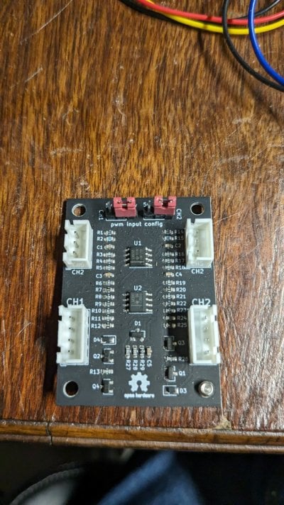
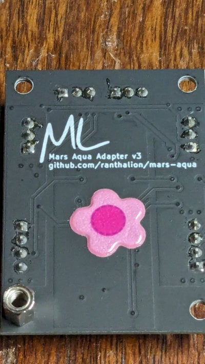
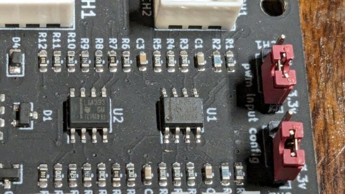
This appears to be a newer version of the board, can you provide a brief description as to how this is working, the old one had an op amp but I do not this one does, see attached pics, let me know if you need some additional pics...

After looking up some part numbers it has lm393 - comparator and lm358 - opamp, still not sure I understand how its taking 12v and doing 0-10v.

PXL_20231211_021230217.jpg PXL_20231211_021349148.jpg PXL_20231211_021305683.jpg
 

Sral

Valuable Member
View Badges
Joined
May 2, 2022
Messages
1,006
Reaction score
978
Location
Germany
Rating - 0%
0   0   0
This appears to be a newer version of the board, can you provide a brief description as to how this is working, the old one had an op amp but I do not this one does, see attached pics, let me know if you need some additional pics...

After looking up some part numbers it has lm393 - comparator and lm358 - opamp, still not sure I understand how its taking 12v and doing 0-10v.

PXL_20231211_021230217.jpg PXL_20231211_021349148.jpg PXL_20231211_021305683.jpg
Well, sounds like it’s doing exactly the same as the schematic that you listed earlier. It smooths the input PWM to DC using a resistor and capacitor and amplifies that by a factor of 3 for the 3.3V setting and a factor of 2 for the 5V setting.
That naturally brings the output to a maximum of 10V, assuming the input never exceeds the 3.3V or 5V ( depending on setting). If you of course input 5V and set for 3.3V, the output tries to reach 15V (3x5V), but hits the input voltage of 12V and can’t exceed that.

The comparator only checks if the output exceeds a certain threshold and then gives the 12V through to the enable.
 
OP
OP
bishoptf

bishoptf

Valuable Member
View Badges
Joined
Jan 1, 2019
Messages
1,349
Reaction score
1,724
Location
Missouri
Rating - 0%
0   0   0
Well, sounds like it’s doing exactly the same as the schematic that you listed earlier. It smooths the input PWM to DC using a resistor and capacitor and amplifies that by a factor of 3 for the 3.3V setting and a factor of 2 for the 5V setting.
That naturally brings the output to a maximum of 10V, assuming the input never exceeds the 3.3V or 5V ( depending on setting). If you of course input 5V and set for 3.3V, the output tries to reach 15V (3x5V), but hits the input voltage of 12V and can’t exceed that.

The comparator only checks if the output exceeds a certain threshold and then gives the 12V through to the enable.
Ah I think I understand a little better on how it's working the 12v is used for the comparator side of things, now I think I understand. Wish I didnt have to feed it 12v at all since its just another input but pwm coming from the rpi should be 3.3 so this should work. I need to bench it up and test it but haven't had time to do it. Thanks for the explanation and will update based on what I find.
 
Back
Top