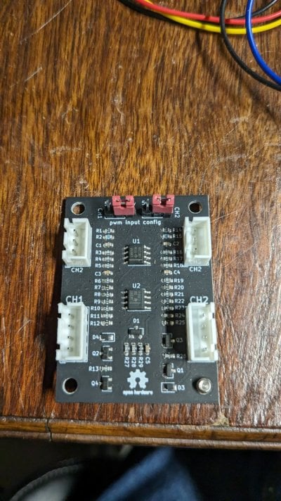
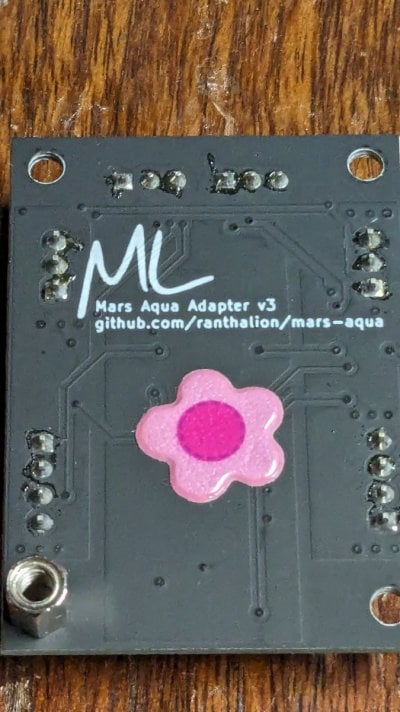
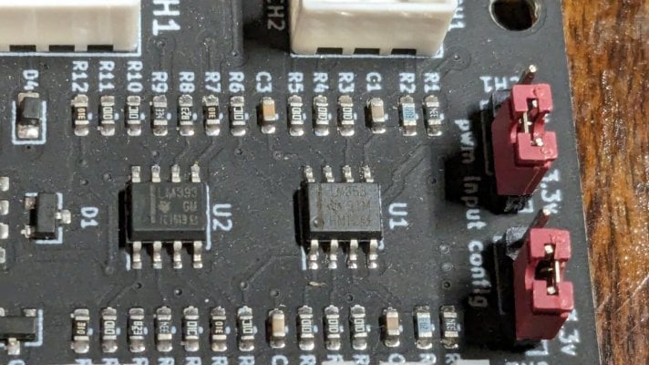
Well after my fun bunny trail adventure trying to control my Nicrew light, once I figured out the factory issue the standard Kessil Lighting diagram will not work properly for the Nicrew lights (the will flicker and pulse no matter the frequency setting). They want to see a much smoother signal than then standard 0-10v pwm that is used for that guide - https://learn.adafruit.com/reef-pi-lighting-controller/circuit-construction but thanks to @Sral he came up with some options that can be applied to that original diagram and make things work. Here is the fritzing diagram:

The additions to @Ranjib original layout (per output) are 1 additional 1k resistor, 1 diode (1n4001) and one 10uF capacitor. For the original part listings see the Adafruit Lighting guide above. @Sral has stated that there are some options to the above diagram that could also be made but I will let him and other throw those options out there. I just wanted to document a basic, easy circuit that I have done and works.
I know these lights are already working in @robsworld78 robotank board but wanted to document this for those that like myself that are still stubbornly rolling our own, lol.


