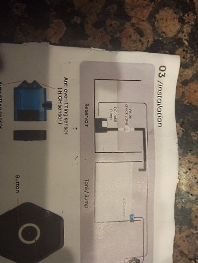
I thought I would share my double float switch setup.
I have two float switches wired in series to a common inlet.
The primary float switch sits in the water. When water evaporates, the buoy sinks, and it triggers the ATO. This is normal operation.
The secondary float switch sits above the water line and the buoy is reversed. That means it triggers when the buoy floats to the top of the sensor (rather than when it sinks).
If a snail or something sits on the primary float switch depressing it and the ATO triggers, it will only fill to the point where the secondary float switch is activated because once the secondary float switch is activated, it will cut off the ATO.
It is much easier to understand with pictures (below). The primary float switch is on the right and the secondary is on the left. I am holding up the wire showing that they are wired together. I attached another pic showing how they were soldered together. Once you twist the two float switch wires together and solder them, you then solder them to your extension wire. This then connects to your hardware (in my case the excellent RoboTank!).
I also use the "disable" option to stop the ATO if it runs for more than a few seconds (I have a small tank).
This setup is a double fail-safe and I haven't had it fail.
Last edited:


