DIY Light with two Meanwell LDD-700L and fan with 4 conductors

reefsAustin

New Member
View Badges
Joined
Feb 11, 2024
Messages
8
Reaction score
0
Location
Austin,TX
Rating - 0%
0   0   0
Hello,

I am making a light with two led strips in a series. One UV and one all the other colors. I have a limitation in that I can only run 4 conductors up to the head of the light that has the LEDS and heat sink. Right now I have it wired so all four conductors are used by the 4 outputs of the LDD-700Ls. However I would like to add a fan to to the heat sink without having to add more conductors as the pipe I am using does not have room for more.

Is there a way to wire the LDD-700Ls such that each channel has independent dimming but uses a common (-) or something along those lines? Such that I can free up a wire to use as a (+) for a fan?

I should also add that the LDD-700Ls are not located on the light head. E.g. I want the drivers etc. to be separate from the light head. Hence why I didn't run the full output of the power supply with just 2 wires and then split it up at the head to multiple drivers. E.g. I want the drivers, the controller and dimming wires in a box separate from the light head. The only wires running to the light head are output wires from the drivers and hopefully a wire for a fan.

Thanks!
 
Last edited:

oreo54

5000 Club Member
View Badges
Joined
Sep 18, 2017
Messages
5,970
Reaction score
3,673
Rating - 0%
0   0   0
Hello,

I am making a light with two led strips in a series. One UV and one all the other colors. I have a limitation in that I can only run 4 conductors up to the head of the light that has the LEDS and heat sink. Right now I have it wired so all four conductors are used by the 4 outputs of the LDD-700Ls. However I would like to add a fan to to the heat sink without having to add more conductors as the pipe I am using does not have room for more.

Is there a way to wire the LDD-700Ls such that each channel has independent dimming but uses a common (-) or something along those lines? Such that I can free up a wire to use as a (+) for a fan?

I should also add that the LDD-700Ls are not located on the light head. E.g. I want the drivers etc. to be separate from the light head. Hence why I didn't run the full output of the power supply with just 2 wires and then split it up at the head to multiple drivers. E.g. I want the drivers, the controller and dimming wires in a box separate from the light head. The only wires running to the light head are output wires from the drivers and hopefully a wire for a fan.

Thanks!
Well off the top of my head remember the ldd's change the voltage out to keep the current stable at 700mA.
This is not very conducive to also running a fan.
So if I think I know what your thinking I think it isn't going to work.

What is the v(f) (@700mA) of the strips you are using?

If you built them you may want to considering a redesign to constant voltage strips. Then you can use a matching fan.
 
OP
OP
R

reefsAustin

New Member
View Badges
Joined
Feb 11, 2024
Messages
8
Reaction score
0
Location
Austin,TX
Rating - 0%
0   0   0
Good point. Does a constant voltage driver support dimming? E.g. it just varies the current output based on dimming signal. In that case the fan would just slow down as the strip got dimmer?
 

oreo54

5000 Club Member
View Badges
Joined
Sep 18, 2017
Messages
5,970
Reaction score
3,673
Rating - 0%
0   0   0
Good point. Does a constant voltage driver support dimming? E.g. it just varies the current output based on dimming signal. In that case the fan would just slow down as the strip got dimmer?
Constant voltage arrays use a resistor as a " driver".
Dimming is usually done with pwm MOSFET switching
Never tried it but I'd assume the fan would slow as the strip is dimmed.
Not sure how say a 50% duty cycle " exactly" effects a fan
Fan would be wired parallel to the led strip.
Your power supply would generally be in the range of 12 to 24v if you want that strip controlled. That's the common parameters of most ticket/ dim units.
Fan voltage to match ..
I'm a " tinker toy" guy not an EE... So keep that in mind here


Not sure it's a good way but don't exactly see a good way here.

I suppose you also could have 1 channel constant current. The fan/color channel constant voltage. Would "probably" require multiple power supplies though..

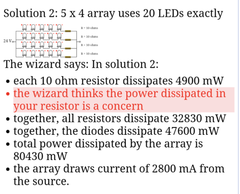
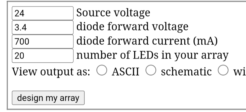
Example array ..

Screenshot_20241017-110215.png Screenshot_20241017-110235.png

Catch us all diodes need to be similarif not equal in voltage.
The closer the additive voltage is to the ps voltage the less " waste" and the smaller wattage resistors

Any cheap controller would work.


Most can also be modified to dim Ldd drivers.
 
Last edited:
OP
OP
R

reefsAustin

New Member
View Badges
Joined
Feb 11, 2024
Messages
8
Reaction score
0
Location
Austin,TX
Rating - 0%
0   0   0
Thanks for helping me think about this. I think I figured out a easy solution. I hooked up just the fan to the LDD to see what would happen. The main power supply is 20v. And sure enough the 12v fan hit 20v. So, not good. So I wired the fan in a series with the leds and it appears to just take "the rest" after the leds. E.g. the LEDs took 13v and the fan then ran on 8v. It appears to just drop in speed when I lower the dimmer signal. So basically. You can just wire the fan in series after the leds and it just kinda works if you have enough head room on the voltage and the fans current rating is higher than the max output of the LDD. I was thinking of putting a switching voltage buck converter in front of the fan to make it pretty bullet proof. You can also add a safety margin by lowering the voltage on the main power supply such that the total adds up to the leds + desired fan voltage. I don't know if this a good setup but I have had it running for a few hours now and nothing is getting hot or blowing up so. Appears like the LDDs drive a fan and leds in series just fine!


oreo54

5000 Club Member
View Badges
Joined
Sep 18, 2017
Messages
5,970
Reaction score
3,673
Rating - 0%
0   0   0
I " believe" that that means your LEDs are not running at 700mA.
Test the current draw...

You can take 18V / # LEDs.
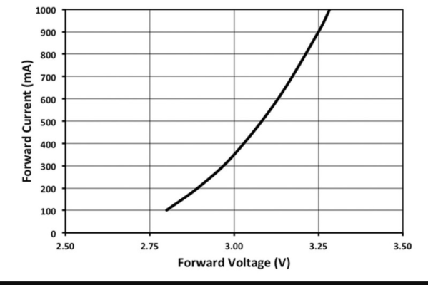
Then check the spec sheet to see approx what current they are running at.
 
OP
OP
R

reefsAustin

New Member
View Badges
Joined
Feb 11, 2024
Messages
8
Reaction score
0
Location
Austin,TX
Rating - 0%
0   0   0
I " believe" that that means your LEDs are not running at 700mA.
Test the current draw...

You can take 18V / # LEDs.
Then check the spec sheet to see approx what current they are running at.
hmm ok I will test it. I thought the whole point of the LDD is that is supplies "constant current" e.g. it sets the voltage of the circuit to maintain the current output set by the dimmer. So if you have 5 LED with 3.3v forward voltage on a max 20v supply. The LDD will set the voltage at 16.5v with 3.5v of headroom at 700ma. So if you add a fan to the series there would only be 3.5v "left" but it would be provided at 700ma. Then when you slide the dimmer it just lowers the ma but not the voltage sent to the circuit.
 

oreo54

5000 Club Member
View Badges
Joined
Sep 18, 2017
Messages
5,970
Reaction score
3,673
Rating - 0%
0   0   0
Step down drivers regulate voltage according to the current demand .

If voltage in is = to voltage out it is likely the current setpoint wasn't reached .
Say you have 6 LEDs that at a 3v V(f) draw 700mA of current you should get a voltage reading of about 18v.
Another example...
There is a minor complications due to heat though.

Screenshot_20241017-174733.png
 
Last edited:
OP
OP
R

reefsAustin

New Member
View Badges
Joined
Feb 11, 2024
Messages
8
Reaction score
0
Location
Austin,TX
Rating - 0%
0   0   0
ok, I went to the junk pile of parts and pulled one of these off an old board.


Basically a voltage regulator that can take up to 35v input and output 8v (measured). I wired the fan to its output and wired the regulator and LED strip in parallel. The fan spins at a good speed and the strip still draws the 700mA. Seems much better. See any problems with this setup?
 

oreo54

5000 Club Member
View Badges
Joined
Sep 18, 2017
Messages
5,970
Reaction score
3,673
Rating - 0%
0   0   0
ok, I went to the junk pile of parts and pulled one of these off an old board.


Basically a voltage regulator that can take up to 35v input and output 8v (measured). I wired the fan to its output and wired the regulator and LED strip in parallel. The fan spins at a good speed and the strip still draws the 700mA. Seems much better. See any problems with this setup?
Well as I said I'm not an electrical engineer so I'm going to put this in more of a question form.
From the spec sheet the dropout voltage is 2V. So the input voltage needs to be 10V or higher to get 8v out.

So what happens when you "average" less than 10V by using pwm?

Granted its really like full voltage or zero voltage. So you should be ok.
It's like on/off...very fast I guess.
 
OP
OP
R

reefsAustin

New Member
View Badges
Joined
Feb 11, 2024
Messages
8
Reaction score
0
Location
Austin,TX
Rating - 0%
0   0   0
Well as I said I'm not an electrical engineer so I'm going to put this in more of a question form.
From the spec sheet the dropout voltage is 2V. So the input voltage needs to be 10V or higher to get 8v out.

So what happens when you "average" less than 10V by using pwm?

Granted its really like full voltage or zero voltage. So you should be ok.
It's like on/off...very fast I guess.
I have two strips. One with two UV leds that pull about 7v 700ma and the other with 4 multi color LEDs. Each has its own LDD for dimming. I put the fan on the UV one. So basically it should just slow down until the LEDs are so low I don't need the fan anyway.
 
Back
Top