
OP
OP
- Joined
- Apr 4, 2021
- Messages
- 1,000
- Reaction score
- 1,102
- Review score
- +0 /0 /-0
- Location
- United Kingdom
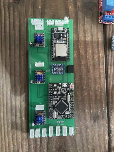
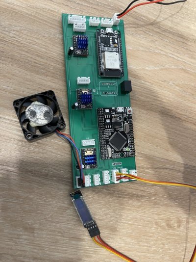
You mean the thing that's circled? It says "Junct" - in my own cryptic language it means "Junction". Nothing goes into that connector - it's merely there to route PCB tracks from one size of PCB into another (sometimes you have no choice but to do that due to space limitations).View attachment 3123805
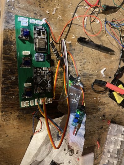
What goes here on my PCB board?