Closed Loop UV Sterilizer System Design

RugerJB

New Member
View Badges
Joined
Nov 29, 2022
Messages
7
Reaction score
1
Location
Houston
Rating - 0%
0   0   0
Hello everyone,
just set my new aquarium on its stand and I'm starting to rough out a plumbing design. We've just received a Planet 310 that I'd added a couple of extra holes for 1" bulkheads in the back glass to feed a closed loop UV system. I've got a Aqua UV Classic 80 watt unit that was plumbed in a previous system that unfortunately has fittings glued to it that limit my install options a bit. My main question is can my UV sterilizer be plumbed on the suction side of my Vectra L2 or should I keep the sterilizer on the return side?
 
OP
OP
R

RugerJB

New Member
View Badges
Joined
Nov 29, 2022
Messages
7
Reaction score
1
Location
Houston
Rating - 0%
0   0   0
I can't really see any downside - other than not having the filter/strainer on the pump beforehand.
Yeah, I’d like to have proper filtration for that loop. I will have strainers in the tank to keep snails and fish out but it’d be nice to have filtration in-line to try to keep the sterilizer clean for longer. I’m not too sure what I could do to achieve that
 
OP
OP
R

RugerJB

New Member
View Badges
Joined
Nov 29, 2022
Messages
7
Reaction score
1
Location
Houston
Rating - 0%
0   0   0
Is the Vectra L2 for the Uv exclusively? By any chance do you have a diagram showing how/where the UV, pump and plumbing will tentatively run?
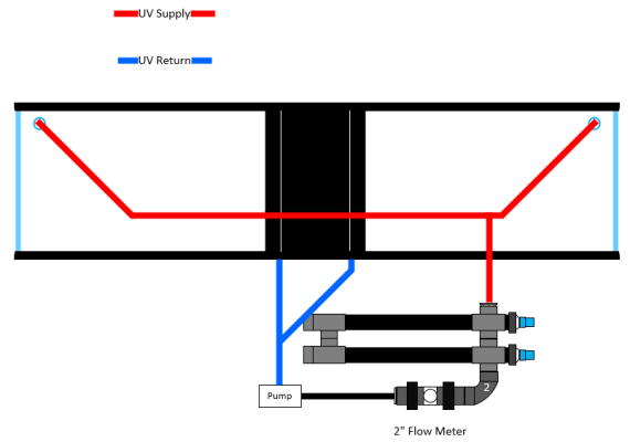
Hi, sorry for the late reply. Work has been crazy today. Here is a basic design strictly for the UV.
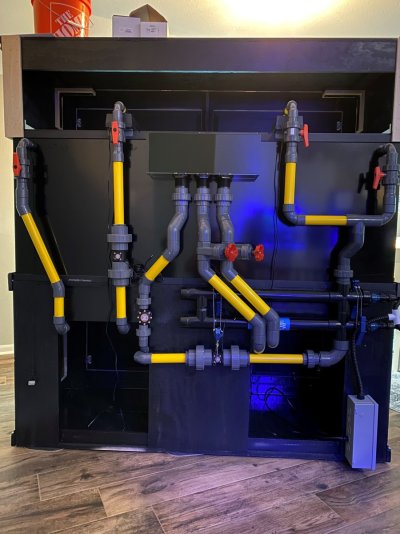
The pump will be outside of the sump against the back of the stand i think. Im considering building an acrylic catch box for it to sit in that is long enough to sit under the sterilizer as well. Last time i ran it it i had the pump in my sump but still in a closed loop. That was the best way to do it for sure. I could take the entire system apart without spilling a drop. The picture is of my 280 that i unfortunately had to get rid of because we moved, but its the same sterilizer.
This go-round ive got an internal overflow with provisions for (5) 1" bulkheads and the additional (2) 1" bulkheads in the traditional return position on the rear top corners. I plan to gravity feed the system through those "return" holes. I had actually done it a similar way last time. The pipe on the top left in the picture was gravity feeding the pump in the sump which discharged into the flow meter then through the UV and up to split between a 1" sea swirl and a 3/4" standard return nozzle.
The filtration part of the new system will have (3) 1" overflows for a standard bean animal style setup into the sump and will be returned with 2 varios 8s, independently, each to their own 1" sea swirl

UV Prelim.PNG Tank pic.jpg
 

Sean Clark

7500 Club Member
View Badges
Joined
May 16, 2019
Messages
8,055
Reaction score
31,606
Location
Michigan
Rating - 0%
0   0   0
Hi, sorry for the late reply. Work has been crazy today. Here is a basic design strictly for the UV.
The pump will be outside of the sump against the back of the stand i think. Im considering building an acrylic catch box for it to sit in that is long enough to sit under the sterilizer as well. Last time i ran it it i had the pump in my sump but still in a closed loop. That was the best way to do it for sure. I could take the entire system apart without spilling a drop. The picture is of my 280 that i unfortunately had to get rid of because we moved, but its the same sterilizer.
This go-round ive got an internal overflow with provisions for (5) 1" bulkheads and the additional (2) 1" bulkheads in the traditional return position on the rear top corners. I plan to gravity feed the system through those "return" holes. I had actually done it a similar way last time. The pipe on the top left in the picture was gravity feeding the pump in the sump which discharged into the flow meter then through the UV and up to split between a 1" sea swirl and a 3/4" standard return nozzle.
The filtration part of the new system will have (3) 1" overflows for a standard bean animal style setup into the sump and will be returned with 2 varios 8s, independently, each to their own 1" sea swirl

UV Prelim.PNG Tank pic.jpg
I certainly hope that you will have full access to the plumbing once this is set in place.
 

Lbrdsoxfan

5000 Club Member
View Badges
Joined
Jun 13, 2021
Messages
5,334
Reaction score
8,469
Location
Long Beach, CA
Rating - 0%
0   0   0
I certainly hope that you will have full access to the plumbing once this is set in place.
This. Changing that bulb(s) is gonna be a bear. I run something similar as all of my return water goes through a 57w aqua UV. Btw, you can contact aqua uv for parts if you want to replace the unions that screw to the unit. Contact them, give the serial number and they send a PDF with a blow up diagram of parts.

I do a simple out from return chamber, through the uv and back to the sump.
 
OP
OP
R

RugerJB

New Member
View Badges
Joined
Nov 29, 2022
Messages
7
Reaction score
1
Location
Houston
Rating - 0%
0   0   0
I certainly hope that you will have full access to the plumbing once this is set in place.
It won’t be fun but I’ll have cepex ball valves at each bulkhead. I’ve not finalized anything yet, but that will definitely be in the final build. I’ll have to space the tank roughly 8” off the wall, so access to those valves won’t be too bad but I’ll need to figure out pipe placement so I can get some unions in between the top bulkhead (my drain or suction for the sterilizer) and where the 2 lines tee into the final drop to the pump. There’s no way I can keep all that plumbing glued as one piece and get it out if I needed to. The sterilizer should be easy to access from the right side of the stand as it will be inside the stand mounted horizontally.
this is basically the area I’m working with
 

Attachments

  • IMG_2044.MOV
    28.7 MB
OP
OP
R

RugerJB

New Member
View Badges
Joined
Nov 29, 2022
Messages
7
Reaction score
1
Location
Houston
Rating - 0%
0   0   0
This. Changing that bulb(s) is gonna be a bear. I run something similar as all of my return water goes through a 57w aqua UV. Btw, you can contact aqua uv for parts if you want to replace the unions that screw to the unit. Contact them, give the serial number and they send a PDF with a blow up diagram of parts.

I do a simple out from return chamber, through the uv and back to the sump.
I am considering adding an extra external chamber to my sump to accommodate a third pump and give a bit more sump volume. The only issue I may run into is how much flow is running through the sump. I’ll probably target around 1250-1500 gph strictly for filtration. I’m positive the sump can handle close to double that mechanically, but I’m concerned that it’ll get fairly noisy.
Here is the sump I’ve got. It’s 50” wide by 22” deep x 18” tall
I’m also seriously considering building another crash box for it to accommodate a reef mat 1200 rather than breaking out the sawzall to the sump.
 

Attachments

  • IMG_2055.MOV
    194.9 KB
OP
OP
R

RugerJB

New Member
View Badges
Joined
Nov 29, 2022
Messages
7
Reaction score
1
Location
Houston
Rating - 0%
0   0   0
I would probably run it in reverse, ie: from the return chamber through the UV and into the tank. That way the water is at least filtered.
I’d really like to and I probably could with a sump modification like I mentioned above. I’d considered building an additional return box and have it piped into the sump’s return section. Currently the return section would have 2 varios 8s for filtered return water so a vectra L2 would definitely not fit in there. I’ve got a feeling that flowing 2500-3000 gph through that sump would be pretty noisy. I’m pretty sure it would flow it though. The additional return chamber idea is attractive for draining the UV circuit though for sure
 

SteveMM62Reef

Valuable Member
View Badges
Joined
Sep 21, 2020
Messages
2,478
Reaction score
1,590
Location
La Plata
Rating - 0%
0   0   0
You need to position the UV so it doesn’t get air bound. In at the bottom Out at the top. Also, I would not install it perfectly Horizontally. I always plug my UV into the same Surge Protection Strip, as the Pump, is on. This will help prevent the Lamp from Frying, on a loss of water flow.
 
OP
OP
R

RugerJB

New Member
View Badges
Joined
Nov 29, 2022
Messages
7
Reaction score
1
Location
Houston
Rating - 0%
0   0   0
You need to position the UV so it doesn’t get air bound. In at the bottom Out at the top. Also, I would not install it perfectly Horizontally. I always plug my UV into the same Surge Protection Strip, as the Pump, is on. This will help prevent the Lamp from Frying, on a loss of water flow.
I’ve decided to do it exactly that way. I will most likely power both as you said. A nice bit of built in safety is always a good thing. I don’t think I would really need the extra flow from the UV circuit when the lamps are off anyway.
 

HAVE YOU EVER KEPT A RARE/UNCOMMON FISH, CORAL, OR INVERT? SHOW IT OFF IN THE THREAD!

  • Yes!

    Votes: 32 45.7%
  • Not yet, but I have one that I want to buy in mind!

    Votes: 9 12.9%
  • No.

    Votes: 26 37.1%
  • Other (please explain).

    Votes: 3 4.3%
Back
Top