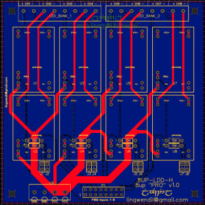
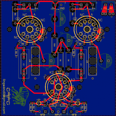
I’m making a PCB board I think I have it done still checking it.
SDA1, SCL1, TXD, RXD will use jumper wires to make the connections, for PH probes one in the calcium reactor one sump.
PMW0, PMW1 will use jumpers to make the connections for the dosing pump motors, this way if I want to use them in a different way I can. I can use the pumps for my calcium reactor one to feed it and one to meter calcium back to tank.
I want to have LEDs come on by float switches but would like the GPIO’s to see the lights come on and report it on the reef-pi screen and by email. (Top right hand of board) same with back up heater.
I put ATO float switch and ATO ds18B20 sensor on it too. Not sure if I will use them on my 300gal. Tank but want them on the PCB. I use a 15 gal top-up box RO-DI water to it by float valve. Than gravity feed by float valve to sump, no pumps, I just want to see light on and email if low water. Other tanks I may use.
8 switch relay connection on left-hand side it uses 5v power for relay switching.
As you can see I have six 0-10v for Mars blue led side, I don’t run the whites, and ten 0-10v for the kessil a360we setup in pairs, I set the PCB board up so those can spit for other light If not using Kessil LEDs, I have two T5 light with two 4’ bulbs on each but they are not dimmable at this time., that may change. The way I put the power to them with a plug it can be change so if some of the lights ever change I can add another PCA9685 breakout board and have some on 0-10v or 0-12v or 0-5v whatever is need for the new lights, kessil a360we can be hook together so I may only use 3 pairs out of 5 on the Kessil lights. And make the T5s dimmable by changing the ballast in each.
All the power is setup so jumpers can hook them together or I can put jumper wires to them I made a board with 3.3v, 5v, 10v, 12v plugs, and I use three LM2596 to set the voltage.
I do not want to use the power from the Raspberry Pi. As they will be in a case with touch screens, I put a 40 pin socket on the PCB board to go to Raspberry Pi I think I will make some 40 pin cable with D-Sub connectors on one end to hook them together.
I think have resistor in series on the GPIOs as needed it’s the one in the top right for the LED lights I’m still trying to figure out, like I was saying I only want those GPIOs to see that the float switch made the connection and the light came on. I think I will need to learn how to write the script for this as I have not found a wright up on it.
I looked at free INSTANT QUOTE here is standard ( or is this better and worth the cost)
PCB prototype:
Gerber file - Gerber_Y2
Layers: 2
Dimension: 200mm*100mm
PCB Qty: 10
PCB Thickness: 1.6 (or is 2 )
Impedance: no
PCB Color: Green
Surface Finish: HASL(withLead) (or leadFree HASL RoHS ) (or ENIG-RoHS)
Copper Weight: 1 oz (or 2 oz)
Gold Fingers: No
Material Details: FR4-Standard Tg 130-140C
Panel By JLCPCB: No
Weight: 810g
Flying Probe Test: Fully Test
Castellated Holes: no


