N-channel Mosfet LED pwm control

bishoptf

Valuable Member
View Badges
Joined
Jan 1, 2019
Messages
1,349
Reaction score
1,724
Location
Missouri
Rating - 0%
0   0   0
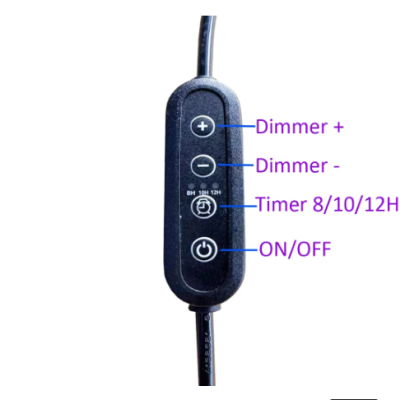
I have controlled 12v led lights before with a N-chaneel mosfet and feed pwm from reef-pi but would like someone to tell me if this would work the same way. I have some led light strips, they are 24vdc input and they have an inline dimmer, see attached pics. The power supply is a 2amp 24v dc power supply. I hooked up my multimeter to the dimmer and looks like low is 13.5v and as you increase the brightness the voltage increases up to 24v. Could I use the same n-lever mosfet to control these lights but feeding 12v vs 12v? What I am thinking is in this case in reef-pi I would set the minimum threshold to say 60% so the range would start around 13v and go up to 24v. Am is missing anything or does that sound logically and should work?

@Sral @theatrus or anyone see any issues with doing that?

Thanks and Happy New Year everyone!
Screenshot at 2024-01-03 09-34-23.png Screenshot at 2024-01-03 09-34-04.png
 

Sral

Valuable Member
View Badges
Joined
May 2, 2022
Messages
1,006
Reaction score
978
Location
Germany
Rating - 0%
0   0   0
I have controlled 12v led lights before with a N-chaneel mosfet and feed pwm from reef-pi but would like someone to tell me if this would work the same way. I have some led light strips, they are 24vdc input and they have an inline dimmer, see attached pics. The power supply is a 2amp 24v dc power supply. I hooked up my multimeter to the dimmer and looks like low is 13.5v and as you increase the brightness the voltage increases up to 24v. Could I use the same n-lever mosfet to control these lights but feeding 12v vs 12v? What I am thinking is in this case in reef-pi I would set the minimum threshold to say 60% so the range would start around 13v and go up to 24v. Am is missing anything or does that sound logically and should work?

@Sral @theatrus or anyone see any issues with doing that?

Thanks and Happy New Year everyone!

Screenshot at 2024-01-03 09-34-23.png Screenshot at 2024-01-03 09-34-04.png
Same to you ;)

This should work fine. I'm a bit confused about the 18 x 3W LEDs ( 54W total ) with actual power of 25W. 54W @ 24V is 2.25A, whereas 25W @ 24V are 1.04A ;
I suspect that you will need to remove the dimmer though. I kind of suspect it to be digital and that wont work well with PWM I suppose. You might first try it anyway and if it doesn't work open up the dimmer and have a look. You might be able to simply use the dimmer and interface that if you are lucky.

Just for clarity:
- When you measured the voltage on the out of the dimmer switch, was the lamp connected ?
- Did you use the DC or the AC setting of the Multimeter ? Please test with both, as that would tell us something about the operation of the dimmer switch.
- Did you mean to write:
control these lights but feeding 12v up to 24V?
Feeding voltage only realy works with a Meanwell ConstantCurrent driver, if I'm not mistaken. If you dimm with PWM on a MOSFET, you always feed 24V, but only for a percentage of time (aka duty cycle). If you measure the DC voltage on the lamp, it will show values between 0 to 24V, depending on the duty cycle.
 
OP
OP
bishoptf

bishoptf

Valuable Member
View Badges
Joined
Jan 1, 2019
Messages
1,349
Reaction score
1,724
Location
Missouri
Rating - 0%
0   0   0
Same to you ;)

This should work fine. I'm a bit confused about the 18 x 3W LEDs ( 54W total ) with actual power of 25W. 54W @ 24V is 2.25A, whereas 25W @ 24V are 1.04A ;
I suspect that you will need to remove the dimmer though. I kind of suspect it to be digital and that wont work well with PWM I suppose. You might first try it anyway and if it doesn't work open up the dimmer and have a look. You might be able to simply use the dimmer and interface that if you are lucky.

Just for clarity:
- When you measured the voltage on the out of the dimmer switch, was the lamp connected ?
- Did you use the DC or the AC setting of the Multimeter ? Please test with both, as that would tell us something about the operation of the dimmer switch.
- Did you mean to write:

Feeding voltage only realy works with a Meanwell ConstantCurrent driver, if I'm not mistaken. If you dimm with PWM on a MOSFET, you always feed 24V, but only for a percentage of time (aka duty cycle). If you measure the DC voltage on the lamp, it will show values between 0 to 24V, depending on the duty cycle.
I measured the output without the lamp connected, just connected my leads to the output of the dimmer and increased/decreased the dimmer function. Based on my readings coming out of the dimmer module bottom was ~13v and tops was almost 24v. I would not run with the dimmer module attached if running from reef-pi, they would be wired direct and then I could control via reef-pi the pwm/percentage.

I used the DC setting, I never think to try with AC setting, I can do that later. And yes I fat fingered the 12v vs 24v wording. What I was trying to say is that I have run these mosfets feeding 12v to a led that has a 12v input, I would assume that the same thing would hold true for 24v, if I fed the mosfet circuit 24v then it would output according to what I have the pwm set for. In this case it looks like I would need to set the minimum limit to 55 to 60% which should be around put my starting voltage around 13-14v, and then I could control it up to 24v which would be 100%. This is the reef-pi setting that I am referring too.

Screenshot at 2024-01-03 10-07-55.png


So are you saying this may not work with the mosfet? Here is a picture of the power supply that its using, looks to me to be just a 2a 24v dc power supply.

PXL_20240103_212951664.jpg


Here is the dimmer module:

PXL_20240103_213555911.jpg


Let me know if this clarified some things...
 

oreo54

5000 Club Member
View Badges
Joined
Sep 18, 2017
Messages
5,970
Reaction score
3,673
Rating - 0%
0   0   0
I have controlled 12v led lights before with a N-chaneel mosfet and feed pwm from reef-pi but would like someone to tell me if this would work the same way. I have some led light strips, they are 24vdc input and they have an inline dimmer, see attached pics. The power supply is a 2amp 24v dc power supply. I hooked up my multimeter to the dimmer and looks like low is 13.5v and as you increase the brightness the voltage increases up to 24v. Could I use the same n-lever mosfet to control these lights but feeding 12v vs 12v? What I am thinking is in this case in reef-pi I would set the minimum threshold to say 60% so the range would start around 13v and go up to 24v. Am is missing anything or does that sound logically and should work?

@Sral @theatrus or anyone see any issues with doing that?

Thanks and Happy New Year everyone!

Screenshot at 2024-01-03 09-34-23.png Screenshot at 2024-01-03 09-34-04.png
None of that is logical at all... well AFAICT.
First there are 2 common ways to run leds. Constant current and constant voltage.

Initially I assumed this is just your standard constant voltage array based on 24v and of course diodes and resistors.
The timer is a simple mosfet switching circuit that chopped the 24v up into itty bitty pieces.. :)
So the dimmer is composed of a small logic circuit, a voltage regulator to power it, and a mosfet as the PWM switch.
Easy peasy..
Just remove the dimmer, use an "appropriate" MOSFET and circuit hooked to the pi..
Also pretty easy peesy.
Well first one needs to confirm that the specs of the mosfet one picks fits what is needed, like fully open at 3.3V (or 5V, whichever is used) and can handle 24V and the amps at 100% duty cycle.

BUT then there is the 2 "mysteries".
1) Why does the controller only dim to 10% and why did you measure the voltage at said 10% to be the AVERAGE of 13.5V.

2) Why would they list the "real" wattage at 25W.
Makes no sense to a constant voltage array that would measure the entire circuit
voltage across the 6 leds and the resistor which would be 24V. The current for a 3w led would probably not be
8.3W per string, 3 strings.
348mA
That would "fit" 1W class leds . Average v(f) of 3.6
3.8 actually works better.
ledsp.JPG

Did they lie stating "3w" leds?
Actually this could matter if you decide to swap leds.

One other semi-oddity for the series. For 18 diodes and assuming 24v the usual string is 5-6 leds. Would seem to fit except for the fact that it uses "violets" which generally have a higher V(f) than rb and blue leds.
Some of the larger units do not divide by 6 but the ps's are???
3.2-3.4v for blue/rb and 3.5-4v for violets. So worst case 4v x 6 = 24V So close enough I guess considering the strings aren't 100% violet.

So though I still believe this is a simple cv array there are some questions that need answering.
As such a simple attachment to a pi

Now the oddly complicated one:
There is a small possibility that the led board has "proper" constant current drivers on the
led board itself.
A 24V CV switching power supply to feed them.
3 with a current set point of say 350mA, no resistors of course.
Or one at 350x 3 (1050mA) but "shared" over 3 parallel strings.
Now that does not usually use an in line dimmer module to chop the input to the drivers though it is a possibility.

Either way the answer is the same. Low side mosfet control
And no.. you cannot change the voltage and have things work well or properly AFAICT.
It either wont work or is completely unnecessary..

You can dim leds in a constant voltage array by using a power supply adjustment but that usually falls in the range of 0 .1 v to maybe 1-2V
You may get away with bit if they happen to use boost drivers but THAT is HIGHLY unlikely. It would be the first I know of.

Try hooking a 12v ps to it with the dimmer removed.. Probably won't light or be real dim.

This is just my way of looking at it.. Corrections are encouraged if anything is illogical.

After proofing this a bit it dawned on me that there is one more remote possibility.
That the dimmer actually contains a "proper" driver.
But it would need to contain not just the driver circuitry but also the full logic circuits to control said driver.
It has been done before though.

BUT, and correct me if I am wrong, light works fine without the dimmer.

Leading back to drivers on board or a simple cv array.

ONE last thing.. If that little dimming box was ACTUALLY dropping the ps voltage from 24v to 13.5V wouldn't that generate a lot of heat?
Equiv to a 30 Ohm resistor (10.5V 350mA), 3.6 watts?


.
 
Last edited:

Sral

Valuable Member
View Badges
Joined
May 2, 2022
Messages
1,006
Reaction score
978
Location
Germany
Rating - 0%
0   0   0
None of that is logical at all... well AFAICT.
First there are 2 common ways to run leds. Constant current and constant voltage.

Initially I assumed this is just your standard constant voltage array based on 24v and of course diodes and resistors.
The timer is a simple mosfet switching circuit that chopped the 24v up into itty bitty pieces.. :)
So the dimmer is composed of a small logic circuit, a voltage regulator to power it, and a mosfet as the PWM switch.
Easy peasy..
Just remove the dimmer, use an "appropriate" MOSFET and circuit hooked to the pi..
Also pretty easy peesy.
Well first one needs to confirm that the specs of the mosfet one picks fits what is needed, like fully open at 3.3V (or 5V, whichever is used) and can handle 24V and the amps at 100% duty cycle.

BUT then there is the 2 "mysteries".
1) Why does the controller only dim to 10% and why did you measure the voltage at said 10% to be the AVERAGE of 13.5V.

2) Why would they list the "real" wattage at 25W.
Makes no sense to a constant voltage array that would measure the entire circuit
voltage across the 6 leds and the resistor which would be 24V. The current for a 3w led would probably not be
8.3W per string, 3 strings.
348mA
That would "fit" 1W class leds . Average v(f) of 3.6
3.8 actually works better.
ledsp.JPG

Did they lie stating "3w" leds?
Actually this could matter if you decide to swap leds.

One other semi-oddity for the series. For 18 diodes and assuming 24v the usual string is 5-6 leds. Would seem to fit except for the fact that it uses "violets" which generally have a higher V(f) than rb and blue leds.
Some of the larger units do not divide by 6 but the ps's are???
3.2-3.4v for blue/rb and 3.5-4v for violets. So worst case 4v x 6 = 24V So close enough I guess considering the strings aren't 100% violet.

So though I still believe this is a simple cv array there are some questions that need answering.
As such a simple attachment to a pi

Now the oddly complicated one:
There is a small possibility that the led board has "proper" constant current drivers on the
led board itself.
A 24V CV switching power supply to feed them.
3 with a current set point of say 350mA, no resistors of course.
Or one at 350x 3 (1050mA) but "shared" over 3 parallel strings.
Now that does not usually use an in line dimmer module to chop the input to the drivers though it is a possibility.

Either way the answer is the same. Low side mosfet control
And no.. you cannot change the voltage and have things work well or properly AFAICT.
It either wont work or is completely unnecessary..

You can dim leds in a constant voltage array by using a power supply adjustment but that usually falls in the range of 0 .1 v to maybe 1-2V
You may get away with bit if they happen to use boost drivers but THAT is HIGHLY unlikely. It would be the first I know of.

Try hooking a 12v ps to it with the dimmer removed.. Probably won't light or be real dim.

This is just my way of looking at it.. Corrections are encouraged if anything is illogical.

After proofing this a bit it dawned on me that there is one more remote possibility.
That the dimmer actually contains a "proper" driver.
But it would need to contain not just the driver circuitry but also the full logic circuits to control said driver.
It has been done before though.

BUT, and correct me if I am wrong, light works fine without the dimmer.

Leading back to drivers on board or a simple cv array.

ONE last thing.. If that little dimming box was ACTUALLY dropping the ps voltage from 24v to 13.5V wouldn't that generate a lot of heat?
Equiv to a 30 Ohm resistor (10.5V 350mA), 3.6 watts?


.
Phew, that’s a lot, but I completely agree with your concerns.

The voltage drop to 13.5V is very weird indeed.
- If it was a simple MOSFET PWM chop, it would go down to below 3V or so in the OFF state.
- So 13.5V sounds like a constant current driver or a capacitor somewhere, although that sounds unnecessarily dangerous ( that capacitor would be stressed a lot).

I don’t think that dropping the 24V to 13V generates a lot of heat, since both a MOSFET and a ConstantCurrent driver would both draw 24V, but pulsed to match the outflowing current to the lamp. So they technically don’t drop 24V to 13.5V like a resistor.
 

Sral

Valuable Member
View Badges
Joined
May 2, 2022
Messages
1,006
Reaction score
978
Location
Germany
Rating - 0%
0   0   0
I measured the output without the lamp connected, just connected my leads to the output of the dimmer and increased/decreased the dimmer function. Based on my readings coming out of the dimmer module bottom was ~13v and tops was almost 24v. I would not run with the dimmer module attached if running from reef-pi, they would be wired direct and then I could control via reef-pi the pwm/percentage.

I used the DC setting, I never think to try with AC setting, I can do that later. And yes I fat fingered the 12v vs 24v wording. What I was trying to say is that I have run these mosfets feeding 12v to a led that has a 12v input, I would assume that the same thing would hold true for 24v, if I fed the mosfet circuit 24v then it would output according to what I have the pwm set for. In this case it looks like I would need to set the minimum limit to 55 to 60% which should be around put my starting voltage around 13-14v, and then I could control it up to 24v which would be 100%. This is the reef-pi setting that I am referring too.

Screenshot at 2024-01-03 10-07-55.png


So are you saying this may not work with the mosfet? Here is a picture of the power supply that its using, looks to me to be just a 2a 24v dc power supply.

PXL_20240103_212951664.jpg


Here is the dimmer module:

PXL_20240103_213555911.jpg


Let me know if this clarified some things...
Clarifying indeed.
The AC voltage test at the lamp set to lowest, mid and highest setting would be clarifying as well.
Another thing I wanted to ask: how many contacts do the connectors have ? Are those simply two Leads each or are there more contacts ?

I think dimming that lamp without the dimmer using an n-Channel MOSFET driven by ReefPi should most likely work, since the lamp is getting 24V in the 100% ON state anyway.

One thing that would likely not work is to expect the PWM setting between 50-100%. It might, if there is an additional capacitor in the lamp itself, but generally in MOSFET dimming you get 0-100% light intensity linearly with 0-100% PWM duty cycle.
 

Sral

Valuable Member
View Badges
Joined
May 2, 2022
Messages
1,006
Reaction score
978
Location
Germany
Rating - 0%
0   0   0
BTW, just for reference:
N-channel MOSFET dimming of an LED lamp is exactly what I did with my Lamp

Problem is that the 100W power supply started whining when I set the 92W lamp to 50% on all channels. I guess the stress on the capacitors is quite high …
 
OP
OP
bishoptf

bishoptf

Valuable Member
View Badges
Joined
Jan 1, 2019
Messages
1,349
Reaction score
1,724
Location
Missouri
Rating - 0%
0   0   0
Clarifying indeed.
The AC voltage test at the lamp set to lowest, mid and highest setting would be clarifying as well.
Another thing I wanted to ask: how many contacts do the connectors have ? Are those simply two Leads each or are there more contacts ?

I think dimming that lamp without the dimmer using an n-Channel MOSFET driven by ReefPi should most likely work, since the lamp is getting 24V in the 100% ON state anyway.

One thing that would likely not work is to expect the PWM setting between 50-100%. It might, if there is an additional capacitor in the lamp itself, but generally in MOSFET dimming you get 0-100% light intensity linearly with 0-100% PWM duty cycle.
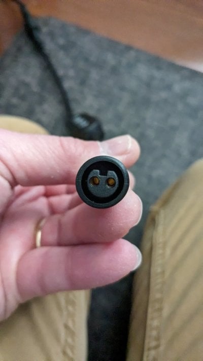
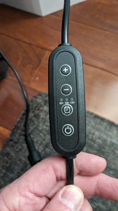
The connector is only a 2wire connector, I also took the voltage in ac mode but acted kind of weird. At the lowest setting in ac mode it read 7.5, mid range 5.5 and at the highest setting it would flash and not read anything, really could only get a reading from mid and low in AC mode. Attached 2 pics, one of the dimmer unit and the other of the end of the cable. The dimmer appears to do 8 steps and the unit has a timer and an on/off button. I wish I had order an additional timer so I could have opened it up but I am using both of them currently.
 

Attachments

  • PXL_20240105_142506889.jpg
    PXL_20240105_142506889.jpg
    91.2 KB · Views: 44
  • PXL_20240105_142518777.jpg
    PXL_20240105_142518777.jpg
    119.3 KB · Views: 65

oreo54

5000 Club Member
View Badges
Joined
Sep 18, 2017
Messages
5,970
Reaction score
3,673
Rating - 0%
0   0   0
The connector is only a 2wire connector, I also took the voltage in ac mode but acted kind of weird. At the lowest setting in ac mode it read 7.5, mid range 5.5 and at the highest setting it would flash and not read anything, really could only get a reading from mid and low in AC mode. Attached 2 pics, one of the dimmer unit and the other of the end of the cable. The dimmer appears to do 8 steps and the unit has a timer and an on/off button. I wish I had order an additional timer so I could have opened it up but I am using both of them currently.
You don't need the dimmer to have the light on correct?
If so then there definitely is no constant current driver inside the dimmer. Plain ole constant voltage dimming up to the light head. Is there more circuitry inside the light itself, other than resistors and shunt diodes?

Don't know suspect not.


There is only one company that ever "pulsed' a power supply followed by constant current drivers on board.
It is an odd way to do it.
Don't know why your meters acting funky but I suspect meter error more than anything at this point.
Could be the switching frequency is screwing with it.

You would need an oscilloscope to accurately define it.
 
OP
OP
bishoptf

bishoptf

Valuable Member
View Badges
Joined
Jan 1, 2019
Messages
1,349
Reaction score
1,724
Location
Missouri
Rating - 0%
0   0   0
Clarifying indeed.
The AC voltage test at the lamp set to lowest, mid and highest setting would be clarifying as well.
Another thing I wanted to ask: how many contacts do the connectors have ? Are those simply two Leads each or are there more contacts ?

I think dimming that lamp without the dimmer using an n-Channel MOSFET driven by ReefPi should most likely work, since the lamp is getting 24V in the 100% ON state anyway.

One thing that would likely not work is to expect the PWM setting between 50-100%. It might, if there is an additional capacitor in the lamp itself, but generally in MOSFET dimming you get 0-100% light intensity linearly with 0-100% PWM duty cycle.
The connector is only a 2wire connector, I also took the voltage in ac mode but acted kind of weird. At the lowest setting in ac mode it read 7.5, mid range 5.5 and at the highest setting it would flash and not read anything, really could only get a reading from mid and low in AC mode. Attached 2 pics, one of the dimmer unit and the other of the end of the cable. The dimmer appears to do 8 steps and the unit has a timer and an on/off button. I wish I had order an additional timer so I could have opened it up but I am using both of them currently
You don't need the dimmer to have the light on correct?
If so then there definitely is no constant current driver inside the dimmer. Plain ole constant voltage dimming up to the light head. Is there more circuitry inside the light itself, other than resistors and shunt diodes?

Don't know suspect not.


There is only one company that ever "pulsed' a power supply followed by constant current drivers on board.
It is an odd way to do it.
Don't know why your meters acting funky but I suspect meter error more than anything at this point.
Could be the switching frequency is screwing with it.

You would need an oscilloscope to accurately define it.
Only happens in a mode and what I think it was telling me was the reading is out of range. Nope, disconnect the dimmer and it goes full blast, I have not opened one of the lights to see what's inside, from what I have read it's filled with gunk to make it ip65 compliant etc...
 

oreo54

5000 Club Member
View Badges
Joined
Sep 18, 2017
Messages
5,970
Reaction score
3,673
Rating - 0%
0   0   0
Only happens in a mode and what I think it was telling me was the reading is out of range. Nope, disconnect the dimmer and it goes full blast, I have not opened one of the lights to see what's inside, from what I have read it's filled with gunk to make it ip65 compliant etc...
Right disconnect the dimmer. light still works and as expected.
As to filled w/ gunk. Well maybe conformal coating on board and a bunch of silicone to seal the plastic lens/body parts.
Technically wouldn't really need both.
But it is why I recommended having them customize it.
 

HAVE YOU EVER KEPT A RARE/UNCOMMON FISH, CORAL, OR INVERT? SHOW IT OFF IN THE THREAD!

  • Yes!

    Votes: 32 45.7%
  • Not yet, but I have one that I want to buy in mind!

    Votes: 9 12.9%
  • No.

    Votes: 26 37.1%
  • Other (please explain).

    Votes: 3 4.3%
Back
Top