JBJ Chiller Modification for External Control

BeanAnimal

5000 Club Member
View Badges
Joined
Jul 16, 2009
Messages
5,071
Reaction score
8,108
Rating - 0%
0   0   0
First and foremost -

DISCLAIMER: I am posting this AS IS - These are not instructions or advice. If you modify a piece of equipment, the design, implementation and responsibility for doing it safely and correctly are all yours. If you don't know exactly what you are doing then you are better of not doing it.

I have a JBJ 1/10 horsepower Chiller. the built in hysteresis is +/- 1 degree Fahrenheit. That means that if the chiller is set at 77 degrees, it will START chilling at 78 degrees and STOP chilling at 76 degrees. That is a 2 degree temperature swing. In my system, on a hot day the chiller may cycle 4-6 times a day. That is a LOT of temperature movement.

The hysteresis is not adjustable. However, I have a GHL Profilux 4 controller that can be set to as low as +/- .13 degrees Fahrenheit. This is a much tighter temperature band. The chiller will run more often, but the temperature swings will be MUCH smaller.

The issue is that if the chiller is plugged into an external temperature controller, then the whole chiller powers on and off with each controller cycle. The chiller has a built in timer that will not let it "chill" for several minutes after turning on. This also means that the display will be "off" with the chiller is off.

Here is the schematic for the chiller. NOTE THAT IT IS WRONG!!!!!!!
1708797125587.png

After taking the chiller apart and becoming utterly confounded with what I saw. It would appear that the line FUSE is on the NEUTRAL side (BRAWN/BROWN). The SKY (LINE) connection is the one tied directly to the COMPRESSOR and FAN and the WHITE wire (SWITCHED WIRE) is the NEUTRAL. The "C" marking on the compressor stands for "common" and is ALWAYS fed by LINE and not NEUTRAL. "M" is the motor winding and the one with "PTC" is the start winding

While this does not change the operation per-say, it does present a deviation from standards. We would typically FUSE and SWITCH the HOT conductor. That way if the fuse blows, the components inside of the machine are no longer live. Likewise in this setup, the compressor and fan ALWAYS have HOT going to them, so even when not running have live voltage to them.

Therefore, in the drawing above the "L" that is connected to "FUSE" and "SKY" is actually "N" (neutral) and the BRAWN/BROWN wire.

"N" in the schematic is actually "L" and NOT connected to BRAWN/BROWN but actually connected to "SKY".


So CONTRARY TO THE SCHEMATIC - this how is the chiller is setup.
SKY = LINE (120V) (mis-marked "N" on drawning)
BROWN = NEUTRAL (120V) (mis-marked "L" on drawing.)


When the controller calls for cooling the WHITE wire is connected to the BROWN (the nuetral) - thus energizing the fan and compressor by completing the circuit.

The modification is rather simple. I built a relay module with a DPDT switch to go in between the "Power Inlet and Comp." and "Temperature Controller" sections shown in the schematic above.

The DPDT switch simply allows the RELAY to control the compressor OR the built in temperature controller to control the compressor. In the drawing below the top line is NEUTRAL (BROWN). The middle line is HOT (SKY) and the bottom line SWITCHED NEUTRAL (WHITE).

1708798963900.png


Left is the Power Inlet - middle is the new module and right is the temperature controller. You can see that the relay coil is not shown connected here. In my case it is a 120V relay and connected to a switched port on my Profilux power bar.

I considered an alternate approaches but decided against them for various reasons. In the schematic below, the top switch position allows for ONLY external control. The bottom switch position allows for EITHER the external or internal temperature controller to turn the chiller on, but BOTH must be off for the chiller to turn off. While these feels like a fail-safe it is confusing and the actual temperature band is hard to map out between the two competing controllers and their set point and hysteresis settings. There are others (not shown) as well.
1708800551993.png


I will post photos of the modification if I get a chance.
 
Last edited:
OP
OP
B

BeanAnimal

5000 Club Member
View Badges
Joined
Jul 16, 2009
Messages
5,071
Reaction score
8,108
Rating - 0%
0   0   0
I completed the modifications and the chiller has been online for 24 hours.
Here is the final schematic showing the changes that I made. as well as the "correct" schematic that represents how the chiller was wired from the factory (as opposed to the schematic published by JBJ)

Top image is the corrected schematic (I did not verify PIN NUMBERS on CONNECTOR MALE 3P/ FEMALE 4P. They could very well be reversed as well.
1708891512207.png


1708884996525.png


I will add that this reinforces my first comment in this thread. If you don't absolutely know what you are doing, blindly following a plan or schematic can be trouble.

This chiller's wiring (from the factory) does not match the schematic made available by the manufacture.
 
Last edited:
OP
OP
B

BeanAnimal

5000 Club Member
View Badges
Joined
Jul 16, 2009
Messages
5,071
Reaction score
8,108
Rating - 0%
0   0   0
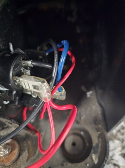
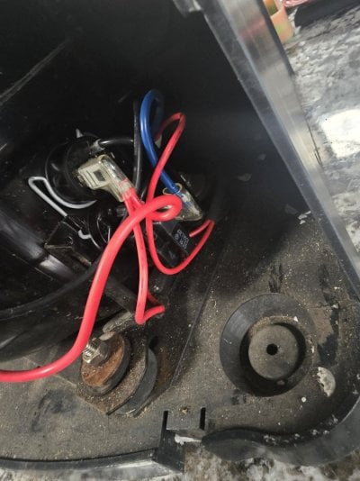
Left factory connection shows SKY coming from the power cord, going out to the 4 pin connector AND connecting to the compressor (brown) and fan (black).

Right factory connection shows WHITE coming from the 4 pin connector and going to the compressor (white) and fan (black).

The is exactly opposite (left connector) of what the factory schematic shows!

Not show (brown from power inlet) goes directly to the 4 pin connector. The left connector was left in-tact and the right connector is the one that I cut, placing the switch in between.
1708884175893.png


The photo below shows the relay installed. I used an existing screw on the condenser case.
1708884434827.png


Waterproof ring terminals crimped (below) before heat shrinking. These will connect to the terminals of the DPDT switch. A note here, you MUST use a ratcheting or commercial grade crimper. Using a pair of pliers or cheap "crimper" never results in a reliable termination.
1708884496743.png


120V 15A DPDT toggle switch show n with one terminal connected.
1708884603991.png
 
Last edited:

static416

Community Member
View Badges
Joined
Mar 26, 2022
Messages
76
Reaction score
50
Location
Toronto
Rating - 0%
0   0   0
This is great. I'm about to get the 1/3 hp model and was worrying about the same thing. My current hysteresis is about 1.5 degrees in the summer, and I want it tighter, which is why I bought it. I didn't realize that the default is 2 degrees! That's much more than I expected.

Also, this would have the benefit of preventing my chiller from fighting my heater if they are on the same controller.
 

static416

Community Member
View Badges
Joined
Mar 26, 2022
Messages
76
Reaction score
50
Location
Toronto
Rating - 0%
0   0   0
Also, it somehow would not have occured to me to verify a provided wiring diagram against the circuit itself. That is smart.
 

static416

Community Member
View Badges
Joined
Mar 26, 2022
Messages
76
Reaction score
50
Location
Toronto
Rating - 0%
0   0   0
Actually, 76-78F is about 24.5C to 25.5C, which is not that bad IMO. But still an order of magnitude more than the 0.1C control I have now with the Inkbird.
 
OP
OP
B

BeanAnimal

5000 Club Member
View Badges
Joined
Jul 16, 2009
Messages
5,071
Reaction score
8,108
Rating - 0%
0   0   0
Also, it somehow would not have occured to me to verify a provided wiring diagram against the circuit itself. That is smart.
Yes - rather bothersome to be honest and poor circuit design as well. Verify and be careful.

My temp holds tight with about .2 swing now. The chiller kicks on a good bit more but I am okay with that.
 

Asthix

Community Member
View Badges
Joined
Oct 20, 2019
Messages
90
Reaction score
62
Rating - 0%
0   0   0
Stupid questions, but wouldn't it be easier to simply set the temperature threshold lower than the actual need (let's say by .5 degree), that way it always turns on when powered by the Inkbird/Profilux, but with another layer of safety?

No pun intended, but I don't see much point of that, except if you don't trust the internal temperature controller to trigger it on.
Still happy to see people going on DIY,
 
OP
OP
B

BeanAnimal

5000 Club Member
View Badges
Joined
Jul 16, 2009
Messages
5,071
Reaction score
8,108
Rating - 0%
0   0   0
The chiller has a 5 minute turn on delay when first powered up (as well as no display).
 

theatrus

Valuable Member
View Badges
Joined
Mar 26, 2016
Messages
2,223
Reaction score
3,632
Location
Sacramento, CA area
Rating - 0%
0   0   0
Stupid questions, but wouldn't it be easier to simply set the temperature threshold lower than the actual need (let's say by .5 degree), that way it always turns on when powered by the Inkbird/Profilux, but with another layer of safety?

No pun intended, but I don't see much point of that, except if you don't trust the internal temperature controller to trigger it on.
Still happy to see people going on DIY,

This is how I used to run the chiller for the longest time, and its not a great model. Arguably it saves a tiny bit of power to not run the display but thats a silly optimization.

First and foremost -

DISCLAIMER: I am posting this AS IS - These are not instructions or advice. If you modify a piece of equipment, the design, implementation and responsibility for doing it safely and correctly are all yours. If you don't know exactly what you are doing then you are better of not doing it.

I have a JBJ 1/10 horsepower Chiller. the built in hysteresis is +/- 1 degree Fahrenheit. That means that if the chiller is set at 77 degrees, it will START chilling at 78 degrees and STOP chilling at 76 degrees. That is a 2 degree temperature swing. In my system, on a hot day the chiller may cycle 4-6 times a day. That is a LOT of temperature movement.

The hysteresis is not adjustable. However, I have a GHL Profilux 4 controller that can be set to as low as +/- .13 degrees Fahrenheit. This is a much tighter temperature band. The chiller will run more often, but the temperature swings will be MUCH smaller.

The issue is that if the chiller is plugged into an external temperature controller, then the whole chiller powers on and off with each controller cycle. The chiller has a built in timer that will not let it "chill" for several minutes after turning on. This also means that the display will be "off" with the chiller is off.

Here is the schematic for the chiller. NOTE THAT IT IS WRONG!!!!!!!
1708797125587.png

After taking the chiller apart and becoming utterly confounded with what I saw. It would appear that the line FUSE is on the NEUTRAL side (BRAWN/BROWN). The SKY (LINE) connection is the one tied directly to the COMPRESSOR and FAN and the WHITE wire (SWITCHED WIRE) is the NEUTRAL. The "C" marking on the compressor stands for "common" and is ALWAYS fed by LINE and not NEUTRAL. "M" is the motor winding and the one with "PTC" is the start winding

While this does not change the operation per-say, it does present a deviation from standards. We would typically FUSE and SWITCH the HOT conductor. That way if the fuse blows, the components inside of the machine are no longer live. Likewise in this setup, the compressor and fan ALWAYS have HOT going to them, so even when not running have live voltage to them.

Therefore, in the drawing above the "L" that is connected to "FUSE" and "SKY" is actually "N" (neutral) and the BRAWN/BROWN wire.

"N" in the schematic is actually "L" and NOT connected to BRAWN/BROWN but actually connected to "SKY".


So CONTRARY TO THE SCHEMATIC - this how is the chiller is setup.
SKY = LINE (120V) (mis-marked "N" on drawning)
BROWN = NEUTRAL (120V) (mis-marked "L" on drawing.)


When the controller calls for cooling the WHITE wire is connected to the BROWN (the nuetral) - thus energizing the fan and compressor by completing the circuit.

The modification is rather simple. I built a relay module with a DPDT switch to go in between the "Power Inlet and Comp." and "Temperature Controller" sections shown in the schematic above.

The DPDT switch simply allows the RELAY to control the compressor OR the built in temperature controller to control the compressor. In the drawing below the top line is NEUTRAL (BROWN). The middle line is HOT (SKY) and the bottom line SWITCHED NEUTRAL (WHITE).

1708798963900.png


Left is the Power Inlet - middle is the new module and right is the temperature controller. You can see that the relay coil is not shown connected here. In my case it is a 120V relay and connected to a switched port on my Profilux power bar.

I considered an alternate approaches but decided against them for various reasons. In the schematic below, the top switch position allows for ONLY external control. The bottom switch position allows for EITHER the external or internal temperature controller to turn the chiller on, but BOTH must be off for the chiller to turn off. While these feels like a fail-safe it is confusing and the actual temperature band is hard to map out between the two competing controllers and their set point and hysteresis settings. There are others (not shown) as well.
1708800551993.png


I will post photos of the modification if I get a chance.


Going to steal this idea, though I do want to buffer the thermistor for in-line temperature feedback for the controller.
 

Asthix

Community Member
View Badges
Joined
Oct 20, 2019
Messages
90
Reaction score
62
Rating - 0%
0   0   0
The chiller has a 5 minute turn on delay when first powered up (as well as no display).
Didn't know about that.
In Europe we mostly use, if not only Teko chiller, they are crazy expensive new but there is plenty of used one.

There is no power on delay whatsoever for them Tk1000 and 2000 that I use just for information.
 

theatrus

Valuable Member
View Badges
Joined
Mar 26, 2016
Messages
2,223
Reaction score
3,632
Location
Sacramento, CA area
Rating - 0%
0   0   0
Didn't know about that.
In Europe we mostly use, if not only Teko chiller, they are crazy expensive new but there is plenty of used one.

There is no power on delay whatsoever for them Tk1000 and 2000 that I use just for information.

Teco exists here too, but is a premium price as well. Most of these units are similar - the old JBJ I had to fix was a Samsung R-134a compressor, but unlike Teco they don't provide service ports on it. Though it looks like new Teco is R290 and those are usually sealed systems (R290 = refrigerant grade Propane)

For the manufacturers, having an external control input would be great ;)
 
OP
OP
B

BeanAnimal

5000 Club Member
View Badges
Joined
Jul 16, 2009
Messages
5,071
Reaction score
8,108
Rating - 0%
0   0   0
Teco exists here too, but is a premium price as well. Most of these units are similar - the old JBJ I had to fix was a Samsung R-134a compressor, but unlike Teco they don't provide service ports on it. Though it looks like new Teco is R290 and those are usually sealed systems (R290 = refrigerant grade Propane)

For the manufacturers, having an external control input would be great ;)
Heck just wiring it to accepted standards and to the schematic would be great....

I looked at Teco and may eventually end up with one but this was a good price and I needed it rather quickly.
 

tknott177

New Member
View Badges
Joined
Jul 19, 2024
Messages
13
Reaction score
1
Location
Deland
Rating - 0%
0   0   0
I completed the modifications and the chiller has been online for 24 hours.
Here is the final schematic showing the changes that I made. as well as the "correct" schematic that represents how the chiller was wired from the factory (as opposed to the schematic published by JBJ)

Top image is the corrected schematic (I did not verify PIN NUMBERS on CONNECTOR MALE 3P/ FEMALE 4P. They could very well be reversed as well.
1708891512207.png


1708884996525.png


I will add that this reinforces my first comment in this thread. If you don't absolutely know what you are doing, blindly following a plan or schematic can be trouble.

This chiller's wiring (from the factory) does not match the schematic made available by the manufacture.
 

tknott177

New Member
View Badges
Joined
Jul 19, 2024
Messages
13
Reaction score
1
Location
Deland
Rating - 0%
0   0   0
Beananimal.

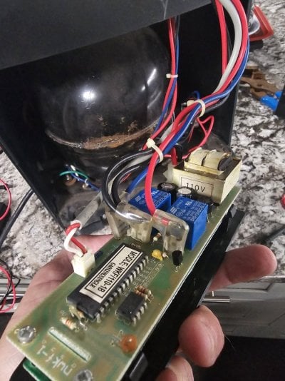
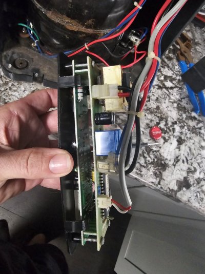
So maybe you can help me out. I've got a quarter horse chiller that definitely has some age on it but I believe it's never been used. I picked it up for next to nothing and noticed the fuse was missing unfortunately I didn't get lucky enough for that to be the issue. When I open the old gal up the transformer was completely off the board. I reseeded the transformer on the pegs hoping that would do the trick as well, unfortunately it's not. I'm getting power all the way up to the transformer or where it should go. I'm trying to figure out a way to use it so I don't have to purchase a different one. I've searched for a board with no luck. Would you be willing to give me any advice? I attached a few photos if you might be able to come up with a solution.
 

Attachments

  • 20240826_205821.jpg
    20240826_205821.jpg
    208.6 KB · Views: 13
  • 20240826_205826.jpg
    20240826_205826.jpg
    201.7 KB · Views: 12
  • 20240826_205852.jpg
    20240826_205852.jpg
    112.9 KB · Views: 18
  • 20240826_205845.jpg
    20240826_205845.jpg
    181.9 KB · Views: 17
OP
OP
B

BeanAnimal

5000 Club Member
View Badges
Joined
Jul 16, 2009
Messages
5,071
Reaction score
8,108
Rating - 0%
0   0   0
I assume that to be the control board - It could be fully bypassed. Without a schematic, I could not begin to safely tell you how from a few photos. In the end the compressor and fan run from 120V and could be controlled from an external temperature controller, preferably through a relay.
 

tknott177

New Member
View Badges
Joined
Jul 19, 2024
Messages
13
Reaction score
1
Location
Deland
Rating - 0%
0   0   0
Okay I assumed I could just use a relay and more less straight wire it. Plug it into an inkbird and call it a day. Thanks man I appreciate you taking that time to respond.
 

HAVE YOU EVER KEPT A RARE/UNCOMMON FISH, CORAL, OR INVERT? SHOW IT OFF IN THE THREAD!

  • Yes!

    Votes: 32 45.7%
  • Not yet, but I have one that I want to buy in mind!

    Votes: 9 12.9%
  • No.

    Votes: 26 37.1%
  • Other (please explain).

    Votes: 3 4.3%
Back
Top