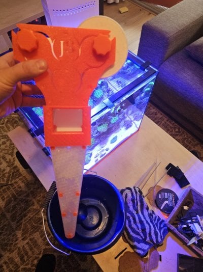
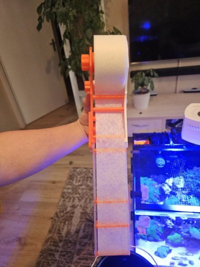
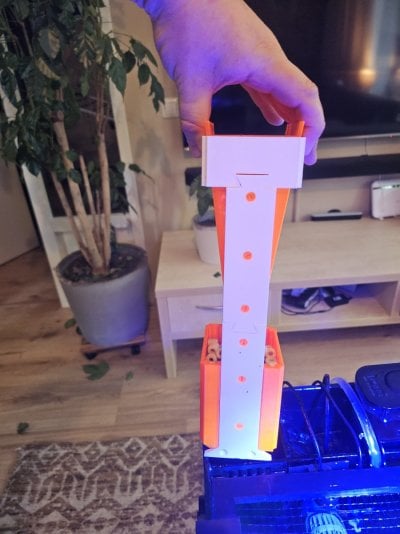
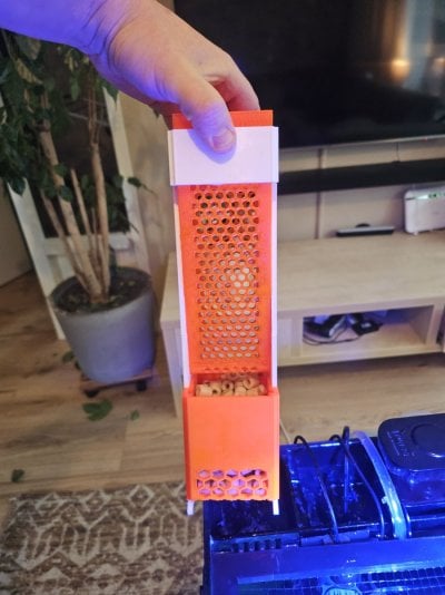
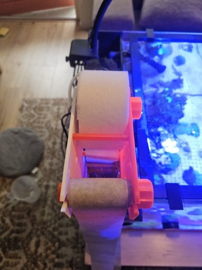
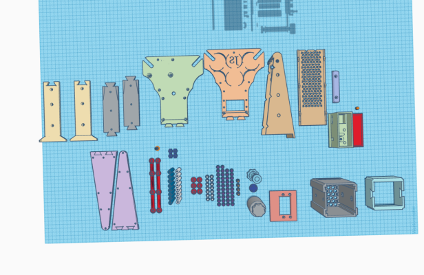
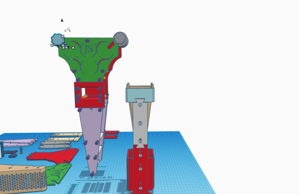
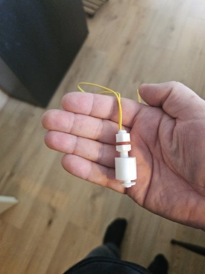
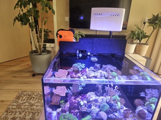
I'm designing a motorised nano fleece rol filter so you don't have to.

ietsjeanders

New Member
View Badges
Joined
May 29, 2024
Messages
18
Reaction score
29
Location
Netherlands
Rating - 0%
0   0   0
Hey Guys,

please know that english is not my native language. I'm sorry if i made grammer errors.

A while back I asked if if was possible to cut a fleece filter rol in half. i've never hold one in my hands at that point. There where some jokes made but that's what started this project.

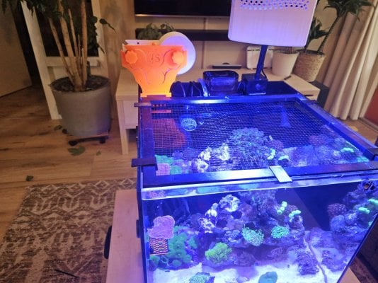
the filter is made for a waterbox nano (cube 10 20 penninsula 15 and 25) but can easily modded in to a different size chamber or even in a small sump ( that does take some modding).

Rightnow I have it working well and i'm waiting for some magnets to arrive to make it motorised. I make this in tinkercad and that does take a lot of time but I do believe it's turning out great.

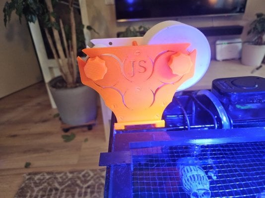
The whole design is screwed together with 3d printed screws. Only the fleece filter basket is glued together because if I want to print it in 1 part it takes 300 grams of support material.
The 2 filter baskets use inserts for the screws. This why the basket can be printed at a lower resolution.

The motor is a 23rpm dc motor from alieexpress and is going to be easily attachable and removable and hold inplace with magnets but the force of winding up the roll is not put upon the magnets.

the motor is turned on and of by 2 water level sensors. 1 in the filter it self and 1 in the chamber next to it ( that one is upside down)
when water in filter is HIGH and the camber next to it is LOW the motor starts turning until the sensors turn off. It's really simple.


The whole project is open source. use it as you like as long as you upload your mods.
20240702_113038.jpg 20240702_113043.jpg 20240702_113103.jpg 20240702_113151.jpg 20240702_113156.jpg 20240702_113222.jpg 20240702_113225.jpg 20240702_113636.jpg filterrol 1 (1).png filterrol 1.png

Edit: here you have the files:

 
Last edited:

Gumbies R Us

Certified Noob
View Badges
Joined
Nov 10, 2022
Messages
14,188
Reaction score
24,058
Location
North Georgia
Rating - 0%
0   0   0
Hey Guys,

please know that english is not my native language. I'm sorry if i made grammer errors.

A while back I asked if if was possible to cut a fleece filter rol in half. i've never hold one in my hands at that point. There where some jokes made but that's what started this project.

the filter is made for a waterbox nano (cube 10 20 penninsula 15 and 25) but can easily modded in to a different size chamber or even in a small sump ( that does take some modding).

Rightnow I have it working well and i'm waiting for some magnets to arrive to make it motorised. I make this in tinkercad and that does take a lot of time but I do believe it's turning out great.

The whole design is screwed together with 3d printed screws. Only the fleece filter basket is glued together because if I want to print it in 1 part it takes 300 grams of support material.
The 2 filter baskets use inserts for the screws. This why the basket can be printed at a lower resolution.

The motor is a 23rpm dc motor from alieexpress and is going to be easily attachable and removable and hold inplace with magnets but the force of winding up the roll is not put upon the magnets.

the motor is turned on and of by 2 water level sensors. 1 in the filter it self and 1 in the chamber next to it ( that one is upside down)
when water in filter is HIGH and the camber next to it is LOW the motor starts turning until the sensors turn off. It's really simple.


The whole project is open source. use it as you like as long as you upload your mods.
20240702_113038.jpg 20240702_113043.jpg 20240702_113103.jpg 20240702_113151.jpg 20240702_113156.jpg 20240702_113222.jpg 20240702_113225.jpg 20240702_113636.jpg filterrol 1 (1).png filterrol 1.png

Edit: here you have the files:

Wow, that is really neat!
 

Jmp998

Well-Known Member
View Badges
Joined
May 3, 2020
Messages
739
Reaction score
977
Rating - 0%
0   0   0
Awesome project-thanks for sharing.
 

theatrus

Valuable Member
View Badges
Joined
Mar 26, 2016
Messages
2,223
Reaction score
3,632
Location
Sacramento, CA area
Rating - 0%
0   0   0
A while back I asked if if was possible to cut a fleece filter rol in half. i've never hold one in my hands at that point. There where some jokes made but that's what started this project.

I remember this thread :) What did you end up using?

Very nice and I like the design a lot. I may actually scale this up a bit for my Nano-20g with a sump.
 
OP
OP
I

ietsjeanders

New Member
View Badges
Joined
May 29, 2024
Messages
18
Reaction score
29
Location
Netherlands
Rating - 0%
0   0   0
Red sea reefmat 500 rolls

I ended up making a 3d printed cylinder with a 3/4 2mm cut out and a very sharp small iron saw.

The design is made so the width can be anywhere from 53 to 58 mm rolls so it doesn't need to be that precise or neat.
 

TX_REEF

Kessil Fanboy
View Badges
Joined
Mar 12, 2023
Messages
3,086
Reaction score
3,642
Location
Texas
Rating - 0%
0   0   0
Hey Guys,

please know that english is not my native language. I'm sorry if i made grammer errors.

A while back I asked if if was possible to cut a fleece filter rol in half. i've never hold one in my hands at that point. There where some jokes made but that's what started this project.

the filter is made for a waterbox nano (cube 10 20 penninsula 15 and 25) but can easily modded in to a different size chamber or even in a small sump ( that does take some modding).

Rightnow I have it working well and i'm waiting for some magnets to arrive to make it motorised. I make this in tinkercad and that does take a lot of time but I do believe it's turning out great.

The whole design is screwed together with 3d printed screws. Only the fleece filter basket is glued together because if I want to print it in 1 part it takes 300 grams of support material.
The 2 filter baskets use inserts for the screws. This why the basket can be printed at a lower resolution.

The motor is a 23rpm dc motor from alieexpress and is going to be easily attachable and removable and hold inplace with magnets but the force of winding up the roll is not put upon the magnets.

the motor is turned on and of by 2 water level sensors. 1 in the filter it self and 1 in the chamber next to it ( that one is upside down)
when water in filter is HIGH and the camber next to it is LOW the motor starts turning until the sensors turn off. It's really simple.


The whole project is open source. use it as you like as long as you upload your mods.
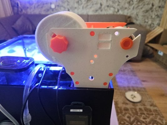
20240702_113038.jpg 20240702_113043.jpg 20240702_113103.jpg 20240702_113151.jpg 20240702_113156.jpg 20240702_113222.jpg 20240702_113225.jpg 20240702_113636.jpg filterrol 1 (1).png filterrol 1.png

Edit: here you have the files:

thank you for your efforts and sharing with the hobby!!!
 

theatrus

Valuable Member
View Badges
Joined
Mar 26, 2016
Messages
2,223
Reaction score
3,632
Location
Sacramento, CA area
Rating - 0%
0   0   0
Red sea reefmat 500 rolls

I ended up making a 3d printed cylinder with a 3/4 2mm cut out and a very sharp small iron saw.

The design is made so the width can be anywhere from 53 to 58 mm rolls so it doesn't need to be that precise or neat.
Beautiful solution
 

Malcontent

Valuable Member
View Badges
Joined
Sep 20, 2018
Messages
1,225
Reaction score
1,200
Rating - 0%
0   0   0
I could not download the files despite already having an Autodesk account and disabling adblockers...
 
OP
OP
I

ietsjeanders

New Member
View Badges
Joined
May 29, 2024
Messages
18
Reaction score
29
Location
Netherlands
Rating - 0%
0   0   0
he files despite already having an Autodesk account and d

you ned to copy and "tinker this" then you can export the parts as 3d printable by selecting them.

you dont want to just download because there is an exploded view with all parts (but some older) and you DON'T want to print or download those:)
 
OP
OP
I

ietsjeanders

New Member
View Badges
Joined
May 29, 2024
Messages
18
Reaction score
29
Location
Netherlands
Rating - 0%
0   0   0
I want to add some building instructions. you need to build the lower part as a whole BEFORE glueing the fleece basket together... otherwise its going to be difficult to keep the inserts inplace while screwing everything together:)
 
OP
OP
I

ietsjeanders

New Member
View Badges
Joined
May 29, 2024
Messages
18
Reaction score
29
Location
Netherlands
Rating - 0%
0   0   0
I made an update to this project. Rightnow I have the motor en sensors working.
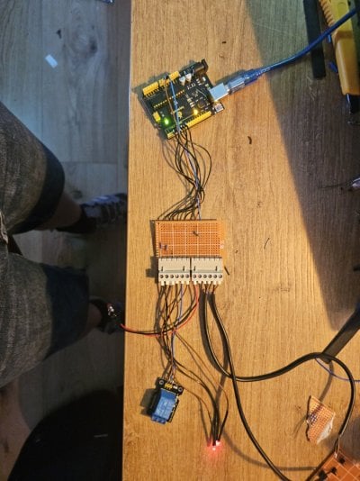
Basicly the 2 water level sensors are switched in series and they connect to the small connection box and that connects to the motor housing. Inside there is a 12v relay and that switches the motor. There is also a button to manually turn on the motor. The motor is locked in to place by magnets. The connection box also connects to the frame by magnets.


I may want to put the motor sideways so it doesn't stick out so much but that is going to give ma a whole new set of problems by having a 90° geared connection and still make it easy to replace a roll.. So rightnow this will have to do.


All files are in the link.


Pics:
1000031189.jpg
1000031190.jpg
1000031182.jpg


1000031201.jpg
 
OP
OP
I

ietsjeanders

New Member
View Badges
Joined
May 29, 2024
Messages
18
Reaction score
29
Location
Netherlands
Rating - 0%
0   0   0
Allright

I'm working on a big update.
I didn't like how it looked and was just to big and bulky.


So I changed the whole top half.
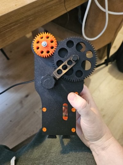
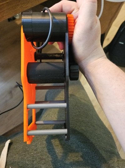
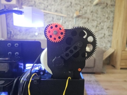
I used a smaller but more powerful motor that fits between the front and back and made gears to turn the fleecefilterrol.

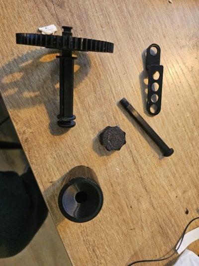
The clean roll fits between the front and back, just like the red sea nano fleece filter. Its put in place by a rod and screw that holds it together. A brace is put in between to hold the rod for the dirty roll in place.

It's easy to replace a roll but does take more steps than the previous version.


The dirty roll comes on top. This whole upgrade is to make it smaller and nicer to look at.


It's a work in progress and when I have it fit I'll post another update with the files.
 

Attachments

  • 20240721_134057.jpg
    20240721_134057.jpg
    148.3 KB · Views: 51
  • 20240721_134103.jpg
    20240721_134103.jpg
    149.1 KB · Views: 48
  • 20240721_134113.jpg
    20240721_134113.jpg
    165 KB · Views: 46
  • 20240721_134154.jpg
    20240721_134154.jpg
    239.9 KB · Views: 49
OP
OP
I

ietsjeanders

New Member
View Badges
Joined
May 29, 2024
Messages
18
Reaction score
29
Location
Netherlands
Rating - 0%
0   0   0
I'm also adding a bit more logic.
I had the problem with the float switches that they were turning the fleece filter motor on and off. And slowly lowering the water in the sump and since the ato is in the aquarium it doesn't get filled up until the filter completely replaced the fleece so the sump level get higher and the aquarium level lowers.

So I need to make something that will run the motor for a longer time.
The thing is. A empty dirty fleece roll takes much longer to replace the fleece than an full one.

So I, with the help of chatgpt made arduino code so that when both sensors are triggered the fleece filter will roll for 20 seconds. Each time the sensors are triggered the amount of time lowers. Until, after 30 cycles it's only 4 seconds. Every cycle run time is equally lowered. A switch resets the cycle (when you replace the roll)
Also 2leds are added to show what sensor is triggered because with my new top half update you can't see the sensor in the filter anymore.

This way it replaces all of the dirty fleece for clean fleece without wasting to much.

It's easy to change the amount of cycles and the start and end time.

I will start testing this tomorrow. Then I'll update.

Also the top half is finished and working really well. Tomorrow I'll add more photos.

Also, when it works well I'll add the code in here in this topic.
 

Attachments

  • 20240723_211508.jpg
    20240723_211508.jpg
    219.7 KB · Views: 64
OP
OP
I

ietsjeanders

New Member
View Badges
Joined
May 29, 2024
Messages
18
Reaction score
29
Location
Netherlands
Rating - 0%
0   0   0
I've got it running and with the arduino it runs way better:) the water levels are way more stable this way.

Also it's way smaller.

I'll update the tinkercad file soon.
 

Attachments

  • 20240726_112534.jpg
    20240726_112534.jpg
    131.6 KB · Views: 55
  • 20240726_112522.jpg
    20240726_112522.jpg
    227.2 KB · Views: 52
OP
OP
I

ietsjeanders

New Member
View Badges
Joined
May 29, 2024
Messages
18
Reaction score
29
Location
Netherlands
Rating - 0%
0   0   0
updated Tinkercad file for version 2.0

parts being used:

motor: 45rpm version.


motor coupler:


water level sensors:


arduino :


5V relais ( 1 needed):


You also can add 2 leds for visual sensor position feedback. Leds turn off when sensor is triggered. ( so its also an indication that system has power)... You do need 2 100ohm resistors for that.


in the arduino code rightnow there are 50 cycles, minimal 4hours in between and first one is 10 seconds long, last one is 3 seconds long.. each of these values can easily be modified.

Arduino code:


// Define pins
const int button1Pin = 2;
const int button2Pin = 3;
const int button3Pin = 4;
const int relayPin = 5;
const int led1Pin = 6;
const int led2Pin = 7;
// Variables for button states
bool button1State = HIGH;
bool button2State = HIGH;
bool button3State = HIGH;

// Debounce variables
unsigned long lastDebounceTime1 = 0;
unsigned long lastDebounceTime2 = 0;
unsigned long lastDebounceTime3 = 0;
const unsigned long debounceDelay = 50; // 50 ms debounce time

// Timer variables
unsigned long lastActivationTime = 0; // Last time the relay was activated
const unsigned long activationInterval = 14400000UL; // 4 hours in milliseconds
bool canActivateRelay = true; // Control if relay can be activated
unsigned long startTime;
unsigned long elapsedTime;
float currentDuration;
int cycleCount = 0;
const int totalCycles = 50;
const float startDuration = 10000; // 10 seconds in milliseconds
const float endDuration = 3000; // 3 seconds in milliseconds

void setup() {
Serial.begin(9600);
pinMode(button1Pin, INPUT_PULLUP);
pinMode(button2Pin, INPUT_PULLUP);
pinMode(button3Pin, INPUT_PULLUP);
pinMode(relayPin, OUTPUT);
pinMode(led1Pin, OUTPUT);
pinMode(led2Pin, OUTPUT);
digitalWrite(relayPin, LOW);
digitalWrite(led1Pin, LOW);
digitalWrite(led2Pin, LOW);
}

void loop() {
unsigned long currentMillis = millis(); // Store current time
// Read button states
bool reading1 = digitalRead(button1Pin);
bool reading2 = digitalRead(button2Pin);
bool reading3 = digitalRead(button3Pin);
// Debounce logic for all buttons
if (currentMillis - lastDebounceTime1 > debounceDelay) {
if (reading1 != button1State) {
lastDebounceTime1 = currentMillis;
button1State = reading1;
}
}
if (currentMillis - lastDebounceTime2 > debounceDelay) {
if (reading2 != button2State) {
lastDebounceTime2 = currentMillis;
button2State = reading2;
}
}
if (currentMillis - lastDebounceTime3 > debounceDelay) {
if (reading3 != button3State) {
lastDebounceTime3 = currentMillis;
button3State = reading3;
if (button3State == LOW) { // Reset the cycle count
cycleCount = 0; // Reset cycle count to restart from the full duration
digitalWrite(relayPin, LOW); // Optionally turn off the relay immediately
Serial.println("Cycle count reset");
}
}
}
// Update activation status based on the interval
if (currentMillis - lastActivationTime >= activationInterval) {
canActivateRelay = true;
}
// Control LEDs based on button states
digitalWrite(led1Pin, button1State == LOW ? HIGH : LOW);
digitalWrite(led2Pin, button2State == LOW ? HIGH : LOW);
// Check if both buttons are pressed and relay activation timer is passed
if (button1State == LOW && button2State == LOW && canActivateRelay) {
canActivateRelay = false; // Prevent further activation
lastActivationTime = currentMillis; // Update last activation time
// Increment the cycle count and calculate the current duration for this cycle
cycleCount = (cycleCount + 1) % totalCycles;
currentDuration = startDuration - ((startDuration - endDuration) / (totalCycles - 1)) * cycleCount;
Serial.print("Starting cycle ");
Serial.println(cycleCount + 1);
Serial.print("Relay ON for ");
Serial.print(currentDuration);
Serial.println(" milliseconds");
digitalWrite(relayPin, HIGH); // Turn on the relay
delay(currentDuration); // Keep the relay on for the calculated duration
digitalWrite(relayPin, LOW); // Turn off the relay
Serial.println("Relay OFF");
}
delay(50); // Small delay to help with debounce and prevent CPU overutilization
}
 
Last edited:
Back
Top