DIY Doser run on digital electric input

Sral

Valuable Member
View Badges
Joined
May 2, 2022
Messages
1,006
Reaction score
978
Location
Germany
Rating - 0%
0   0   0
I want to build a DIY Doser, similarly to the Adafruit Guide. Sadly I couldn't find L293 ICs, so I decided to run with standard monodirectional bipolar transistors (ULN2801 with input resistors).

The current plan and circuit diagram can be found on my project's GitHub page.

A few quirks:
  • I'm concerned about the PCA9685's reliability over I2C, I therefore want to run the pumps on the PI's GPIOs
  • My Pumpsrun nominally on 12V, 200-300mA and 100ml/min, e.g. 0.6s / ml
    • I'm concerned that this is way to fast for typical daily dosing of trace elements
    • I therefore have several methods, as far as I can see
      • dose less often with a then higher amount
      • dose more often, but with diluted fluid (as @Ranjib)
      • decrease the pumps' speed
  • I'm currently favoring to decrease the pump speed
    • I could do this via PWM
      • uses more parts and makes the circuit more complicated
    • I could simply run the pumps with 5V instead of the nominal 12V
      • If the resistance stays the same (which it probably won't) I decrease the electrical power by ( 5v/12V )^2 which is about 1/100
      • that means I would instead of dosing 1ml every 0.6 seconds, dose 1ml every 6-60 seconds, depending on how the pump reacts
Has anybody any experience in running a peristaltic pump on 5V instead of 12V ?
I remember @robsworld78 mentioning something like this in one of his great videos here.
 
Last edited:
OP
OP
S

Sral

Valuable Member
View Badges
Joined
May 2, 2022
Messages
1,006
Reaction score
978
Location
Germany
Rating - 0%
0   0   0
For convenience: this is my current circut idea:
DosingCircuit_schem.png

The Pi unit (link to diagram) that feeds the GPIO input will have the same limit resistors as well, to protect them from short circuits. In total this will make 2.6k, which is close enough to the recommended 2.7k input resistance for 3.3 to 5V TTL. This will be enough current input to switch both 80-125 mA (@5V) and 200-300 mA (@12V), which requires something like 500µA (to calculate, Pi GPIOs have 3.3V and the transistor input is one diode drop above GND so approximately: (3.3V - 0.8V)/2.6k ~ 1mA ).

I'm thinking of leaving some space between the limit resistors and the ULN2803, so I'll be able to later include PWM dimming if I want to. This would be done by simply pulling the IN contacts to GND with a MOSFET that's run constantly by a PWM signal from either the PI or a PCA9685 PWM IC.
 
Last edited:
OP
OP
S

Sral

Valuable Member
View Badges
Joined
May 2, 2022
Messages
1,006
Reaction score
978
Location
Germany
Rating - 0%
0   0   0
As it’s so often the case, writing this I just thought about a solution: just test it out ^^

So I hooked up one pump to my power supply and tested it against a ml syringe. The syringe will put some load on and decrease the flow, but it will allow me to make some estimates.
AF8A3447-782B-4D32-A9BF-BC91DDBDDEB8.jpeg

With or without syringe the pump draws pretty much the same current anyways.

@12V draw is about 310mA for about 12ml in 10s
@ 5V draw is about 240mA for about 4ml in 10s

That’s In line with what I read online, e.g. that RPM and voltage are more or less linear to each other and RPM directly translates to flow. So if I reduce Voltage from 12V to 5V I also reduce flow from about 0.6s/ml to about 1.44s/ml.
 

Ranjib

7500 Club Member
View Badges
Joined
Apr 16, 2016
Messages
9,848
Reaction score
17,081
Location
Pleasant Hill, Concord
Rating - 0%
0   0   0
I had considered 5v pumps, but then didn’t opt for it as they are less common and would involve more amp draw
 
OP
OP
S

Sral

Valuable Member
View Badges
Joined
May 2, 2022
Messages
1,006
Reaction score
978
Location
Germany
Rating - 0%
0   0   0
I had considered 5v pumps, but then didn’t opt for it as they are less common and would involve more amp draw
They are still 12V pumps, I am simply thinking of running them with 5V to reduce the flow per time so I can dose small amounts of trace elements more reliably.
 

Wolfw28

Active Member
View Badges
Joined
Mar 13, 2022
Messages
201
Reaction score
139
Location
Myakka City
Rating - 0%
0   0   0
I want to build a DIY Doser, similarly to the Adafruit Guide. Sadly I couldn't find L293 ICs, so I decided to run with standard monodirectional bipolar transistors (ULN2801 with input resistors).

The current plan and circuit diagram can be found on my project's GitHub page.

A few quirks:
  • I'm concerned about the PCA9685's reliability over I2C, I therefore want to run the pumps on the PI's GPIOs
  • My Pumpsrun nominally on 12V, 200-300mA and 100ml/min, e.g. 0.6s / ml
    • I'm concerned that this is way to fast for typical daily dosing of trace elements
    • I therefore have several methods, as far as I can see
      • dose less often with a then higher amount
      • dose more often, but with diluted fluid (as @Ranjib)
      • decrease the pumps' speed
  • I'm currently favoring to decrease the pump speed
    • I could do this via PWM
      • uses more parts and makes the circuit more complicated
    • I could simply run the pumps with 5V instead of the nominal 12V
      • If the resistance stays the same (which it probably won't) I decrease the electrical power by ( 5v/12V )^2 which is about 1/100
      • that means I would instead of dosing 1ml every 0.6 seconds, dose 1ml every 6-60 seconds, depending on how the pump reacts
Has anybody any experience in running a peristaltic pump on 5V instead of 12V ?
I remember @robsworld78 mentioning something like this in one of his great videos here.
Sounds awesome following would love it if you could figure out how to reverse the direction of the pump also without a large amount of parts and relays.
 

robsworld78

Well-Known Member
View Badges
Joined
Feb 14, 2020
Messages
985
Reaction score
1,325
Location
Edmonton, Canada
Rating - 0%
0   0   0
Looks like he's having fun. :) 5v sounds a little low for a 12v pump, on my controller the ports turn down to 6v but the motor starts making noises and has trouble starting up. I've had a few cheap versions and some run better than others so mileage will vary. If you go this route maybe have the minimum 7v. Either way I'm sure you'll come up with something. :)
 
OP
OP
S

Sral

Valuable Member
View Badges
Joined
May 2, 2022
Messages
1,006
Reaction score
978
Location
Germany
Rating - 0%
0   0   0
Looks like he's having fun. :) 5v sounds a little low for a 12v pump, on my controller the ports turn down to 6v but the motor starts making noises and has trouble starting up. I've had a few cheap versions and some run better than others so mileage will vary. If you go this route maybe have the minimum 7v. Either way I'm sure you'll come up with something. :)
Yes, I am :D
How exactly do you turn the voltage down, while still providing 240mA ?
 
OP
OP
S

Sral

Valuable Member
View Badges
Joined
May 2, 2022
Messages
1,006
Reaction score
978
Location
Germany
Rating - 0%
0   0   0
Sounds awesome following would love it if you could figure out how to reverse the direction of the pump also without a large amount of parts and relays.
Well, the easiest option would be to use a Push-Pull circuit like the L293D or the SN754410 (with added protection diodes), as it's used in the adafruit guide. You could upgrade the guide's version by adding 2 n-channel MOSFETs and thereby reduce the number of GPIOs for directionality selection to 2.

You could also build the push-pull circuit yourself with the same ULN2801 (8 npn darlington transistors) and a similar array of 8 pnp darlington transistors, but those seem to be much less common. one n channel and one p channel MOSFET array or a complementary n+p channel MOSFET array would work as well.

An example for a push-pull circuit would be this H-bridge motor driver IC, here's the datasheet. It does basically almost the same as the L293D, just without the enable pin, so if you want PWM drive you need a few tricks or extra signal components (I'm thinking of 2 MOSFETs, a diode and a few resistors) as such:

MotorControl_Bidirectional_schem.png


The only easier option I see would be a motor driver IC with an enable pin, like the L293D or the SN754410 (the later needs dedicated kickback diodes).
 

Wolfw28

Active Member
View Badges
Joined
Mar 13, 2022
Messages
201
Reaction score
139
Location
Myakka City
Rating - 0%
0   0   0
I want to build a DIY Doser, similarly to the Adafruit Guide. Sadly I couldn't find L293 ICs, so I decided to run with standard monodirectional bipolar transistors (ULN2801 with input resistors).

The current plan and circuit diagram can be found on my project's GitHub page.

A few quirks:
  • I'm concerned about the PCA9685's reliability over I2C, I therefore want to run the pumps on the PI's GPIOs
  • My Pumpsrun nominally on 12V, 200-300mA and 100ml/min, e.g. 0.6s / ml
    • I'm concerned that this is way to fast for typical daily dosing of trace elements
    • I therefore have several methods, as far as I can see
      • dose less often with a then higher amount
      • dose more often, but with diluted fluid (as @Ranjib)
      • decrease the pumps' speed
  • I'm currently favoring to decrease the pump speed
    • I could do this via PWM
      • uses more parts and makes the circuit more complicated
    • I could simply run the pumps with 5V instead of the nominal 12V
      • If the resistance stays the same (which it probably won't) I decrease the electrical power by ( 5v/12V )^2 which is about 1/100
      • that means I would instead of dosing 1ml every 0.6 seconds, dose 1ml every 6-60 seconds, depending on how the pump reacts
Has anybody any experience in running a peristaltic pump on 5V instead of 12V ?
I remember @robsworld78 mentioning something like this in one of his great videos here.
Don't forget that you can change the flow rate by changing the ID of the tubing. Just a thought.
 
OP
OP
S

Sral

Valuable Member
View Badges
Joined
May 2, 2022
Messages
1,006
Reaction score
978
Location
Germany
Rating - 0%
0   0   0
Don't forget that you can change the flow rate by changing the ID of the tubing. Just a thought.
Blimey, didn't think about that, thanks !
I opened one up and it is actually fairly easy. Now I just need to find a tube with the same OD, but smaller ID ... XD

Not sure if I end up doing that, but it's worth pursuing it on the side.
 
OP
OP
S

Sral

Valuable Member
View Badges
Joined
May 2, 2022
Messages
1,006
Reaction score
978
Location
Germany
Rating - 0%
0   0   0
Sounds awesome following would love it if you could figure out how to reverse the direction of the pump also without a large amount of parts and relays.
If you realy want bidirectionality with as little parts as possible, the L9110 mentioned above is the way to go, if you can't find the L293D or SN754410.
Just had a look though: you seem to be able to get some L293D on Amazon, even though other vendors have run out.
 
OP
OP
S

Sral

Valuable Member
View Badges
Joined
May 2, 2022
Messages
1,006
Reaction score
978
Location
Germany
Rating - 0%
0   0   0
I just use N mosfets controlled by PWM. I've tried the L293 but it had the same results so didn't use it.
I guess you also included a capacitor parallel to the load, right ?

Personally I would be slightly concerned that this causes a big load in a switching event, which puts a strain on the MOSFET and drains your bypass capacitors on the 12V line rather quickly, depending on the relative size. However, the fact that you run this setup seemingly without problems indicates that I'm probably just paranoid :rolling-on-the-floor-laughing:
 

robsworld78

Well-Known Member
View Badges
Joined
Feb 14, 2020
Messages
985
Reaction score
1,325
Location
Edmonton, Canada
Rating - 0%
0   0   0
I guess you also included a capacitor parallel to the load, right ?

Personally I would be slightly concerned that this causes a big load in a switching event, which puts a strain on the MOSFET and drains your bypass capacitors on the 12V line rather quickly, depending on the relative size. However, the fact that you run this setup seemingly without problems indicates that I'm probably just paranoid :rolling-on-the-floor-laughing:
I'm actually not using caps on the DC ports as it gets powered directly from the power supply so it doesn't affect anything. I have a large electronic DC load and have done some pretty good stress tests. A couple years ago I had the occasional mosfet short out, I added an extra TVS diode across the source and gate and one hasn't failed since that I know of. I also have a TVS across the source and drain and then a beefy kickback diode. I do have quite a few 100uf can caps on the controller, 2 when the 12v comes in, 2 right after the p channel mosfet for reverse polarity and 2 when the 5v comes out the 5v buck. I also have one next to the 5v pins on the Pi. Overall the noise levels on all rails is very low even with switching and I'm happy to say since v3.0 I haven't had anything fail unless it was water or hook up backwards. One weakness is the DC ports have no reverse polarity protection, once I tried adding a large basic diode to keep cost down but they got hot with 3+ amps even though rated for 8amps so I dumped them. The 5v rail on controller and sensor extension are fully protected and a 2 amp resettable fuse. Now I'm working on v4.0. :)
 
OP
OP
S

Sral

Valuable Member
View Badges
Joined
May 2, 2022
Messages
1,006
Reaction score
978
Location
Germany
Rating - 0%
0   0   0
I'm actually not using caps on the DC ports as it gets powered directly from the power supply so it doesn't affect anything. I have a large electronic DC load and have done some pretty good stress tests. A couple years ago I had the occasional mosfet short out, I added an extra TVS diode across the source and gate and one hasn't failed since that I know of. I also have a TVS across the source and drain and then a beefy kickback diode. I do have quite a few 100uf can caps on the controller, 2 when the 12v comes in, 2 right after the p channel mosfet for reverse polarity and 2 when the 5v comes out the 5v buck. I also have one next to the 5v pins on the Pi. Overall the noise levels on all rails is very low even with switching and I'm happy to say since v3.0 I haven't had anything fail unless it was water or hook up backwards. One weakness is the DC ports have no reverse polarity protection, once I tried adding a large basic diode to keep cost down but they got hot with 3+ amps even though rated for 8amps so I dumped them. The 5v rail on controller and sensor extension are fully protected and a 2 amp resettable fuse. Now I'm working on v4.0. :)
Nice, not sure if it’s a good idea to have caps before reverse polarity protection, as you might blow them with the reverse polarity if they are electrolytic.

could you provide me with a diagram of those DC ports ? I’m thinking of adding the same diodes across my MOSFETs just to be sure, now that you mention them.

That confit on the DC ports does however mean that you run them not as Analog DC, but 12V PWM, right ?
 

robsworld78

Well-Known Member
View Badges
Joined
Feb 14, 2020
Messages
985
Reaction score
1,325
Location
Edmonton, Canada
Rating - 0%
0   0   0
Nice, not sure if it’s a good idea to have caps before reverse polarity protection, as you might blow them with the reverse polarity if they are electrolytic.

could you provide me with a diagram of those DC ports ? I’m thinking of adding the same diodes across my MOSFETs just to be sure, now that you mention them.

That confit on the DC ports does however mean that you run them not as Analog DC, but 12V PWM, right ?
Dohhh, thanks for pointing that out with the caps, guess I better move them to the other side of the reverse polarity. :) Thankfully it's not easy to power up backwards but yeah...

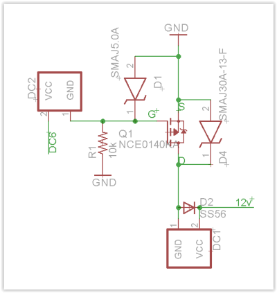
I attached the schematic for the DC ports. The ports are analog DC, just the mosfet gates are driven by 0-5v PWM so you can adjust the output of the mosfet. The mosfets I'm currently using have a bit of a high VGS threshold that's why they only go down to 6v. With a lower VGS they can operate as low as 2v.
 

Attachments

  • Screen Shot 01-07-23 at 11.25 PM.PNG
    Screen Shot 01-07-23 at 11.25 PM.PNG
    18 KB · Views: 49
OP
OP
S

Sral

Valuable Member
View Badges
Joined
May 2, 2022
Messages
1,006
Reaction score
978
Location
Germany
Rating - 0%
0   0   0
Dohhh, thanks for pointing that out with the caps, guess I better move them to the other side of the reverse polarity. :) Thankfully it's not easy to power up backwards but yeah...

I attached the schematic for the DC ports. The ports are analog DC, just the mosfet gates are driven by 0-5v PWM so you can adjust the output of the mosfet. The mosfets I'm currently using have a bit of a high VGS threshold that's why they only go down to 6v. With a lower VGS they can operate as low as 2v.
Hm, I'm having a few troubles deciphering this.

So DC2 is simply the PCA9685's PWM signal, I guess. the MOSFET is an n_channel, but it seems that the internal diode is the wrong way around ? But maybe that just represents the breakdown voltage as a zener diode, what do I know, it does work after all ^^

You protect the Gate by a diode D1 to Ground, that's what I'll try to do as well If I have the space. Might only be relevant for driving capacitive or inductive loads though. Kickback Diode D4 is straightforward as well.

Still, you basically drive the DC1 port like I do my LED lamps, provide V+ and pull the other lead down to GND with a n-channel MOSFET. That sounds to me like a PWM drive at 12V, as there is no active element that stores voltage or current (e.g. a capacitor or inductor) for the phases when the MOSFET is off, except for the MOSFET's and diodes' internal capacitances.

The high VGS threshold should to my knowledge only be a problem insofar, as the PCA9685 might have problems charging the gate up to this point in the time it has during the PWM cycle, since it probably is current limited by a resistor, right ?
 

robsworld78

Well-Known Member
View Badges
Joined
Feb 14, 2020
Messages
985
Reaction score
1,325
Location
Edmonton, Canada
Rating - 0%
0   0   0
Hm, I'm having a few troubles deciphering this.

So DC2 is simply the PCA9685's PWM signal, I guess. the MOSFET is an n_channel, but it seems that the internal diode is the wrong way around ? But maybe that just represents the breakdown voltage as a zener diode, what do I know, it does work after all ^^

You protect the Gate by a diode D1 to Ground, that's what I'll try to do as well If I have the space. Might only be relevant for driving capacitive or inductive loads though. Kickback Diode D4 is straightforward as well.

Still, you basically drive the DC1 port like I do my LED lamps, provide V+ and pull the other lead down to GND with a n-channel MOSFET. That sounds to me like a PWM drive at 12V, as there is no active element that stores voltage or current (e.g. a capacitor or inductor) for the phases when the MOSFET is off, except for the MOSFET's and diodes' internal capacitances.

The high VGS threshold should to my knowledge only be a problem insofar, as the PCA9685 might have problems charging the gate up to this point in the time it has during the PWM cycle, since it probably is current limited by a resistor, right ?
Yeah DC2 is the backup port for a switch like a float, it simply cuts the 0-5v PWM signal to the mosfet, without a signal the pulldown resistor shuts off the mosfet. Sorry for the confusion, the symbol for the mosfet isn't correct, they don't have any internal diodes. The diodes are good for ESD protection, I suspect that was the problem I had. There is a 220 ohm current limit resistor on each PWM output. I'm not up to all the electronic lingo so it's possible it's a PWM drive at 12v. :)
 
OP
OP
S

Sral

Valuable Member
View Badges
Joined
May 2, 2022
Messages
1,006
Reaction score
978
Location
Germany
Rating - 0%
0   0   0
Yeah DC2 is the backup port for a switch like a float, it simply cuts the 0-5v PWM signal to the mosfet, without a signal the pulldown resistor shuts off the mosfet. Sorry for the confusion, the symbol for the mosfet isn't correct, they don't have any internal diodes. The diodes are good for ESD protection, I suspect that was the problem I had. There is a 220 ohm current limit resistor on each PWM output. I'm not up to all the electronic lingo so it's possible it's a PWM drive at 12v. :)
Ah, great, that means my electronics "knowledge" hasn't failed me. Even if is is 12V PWM, as long as it works, it's fine ^^

Another thing I noticed: if you measure this, the load together with the stray capacitances will probably impact the waveform of the 12V PWM, depending on the actual load impedance, inductance and capacitance involved. That way you might get different results from measuring directly with a multimeter/oscilloscope (high impedance) or with an actual load (a 1k resistor being comparatively "low impedance" or a DC motor that is even lower impedance with additional inductance).

Additionally I had a go at calculating the sh** out of a DC motor run at different DC voltages. It rurns our that one has to account for the fact that the load is not linear with the water flow,e.g. double the water flow requires a bit more than double the power, similar to air drag in a car. Otherwise the current draw at 5V and 12V would need to be the same for identical loads, but running slower at 5V.
This is the result:
image.jpg

As you can see the formulas reproduce the measured performance in the top right corner very well.

Simply measure winding resistance with a multimeter, stall voltage with an adjustable power supply and current draw at nominal voltage and you can calculate the performance change at different DC voltages. Flow is proportional to motor frequency. Motor frequency is proportional to voltage above the stall voltage. Current also increases linearly with voltage, but increases slower as soon as the motor starts moving, where the current is equal to V_stall divided by winding resistance.

Mind that this only holds true for DC voltage, or DC voltage with a limiting resistor (you’ll probably have to use the sum of R_motor and R_limit in the formulas) not for a PWM drive.

Although thinking about it, it might actually be very similar for PWM at a constant frequency, just with a higher „stall duty cycle“ instead of a „stall voltage“.
 
Last edited:
Back
Top