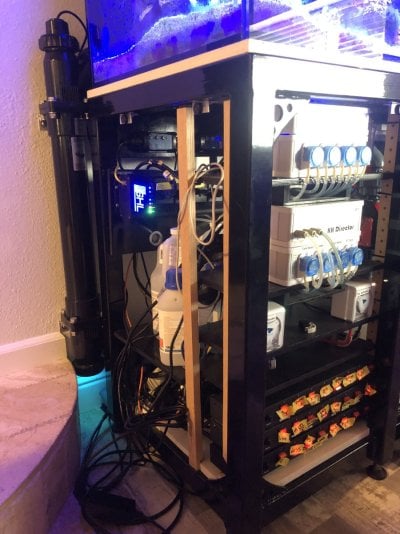
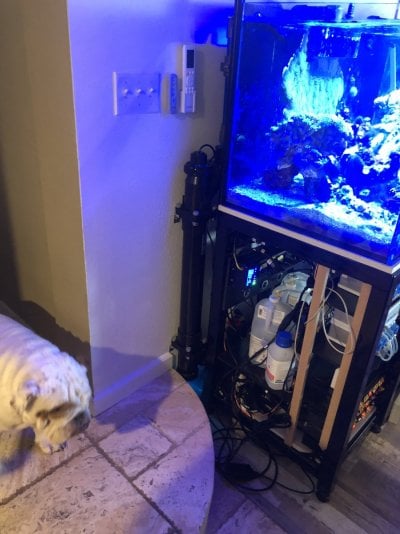
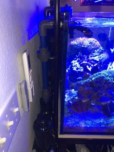
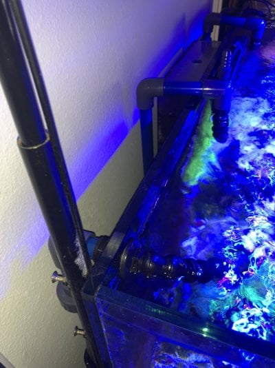
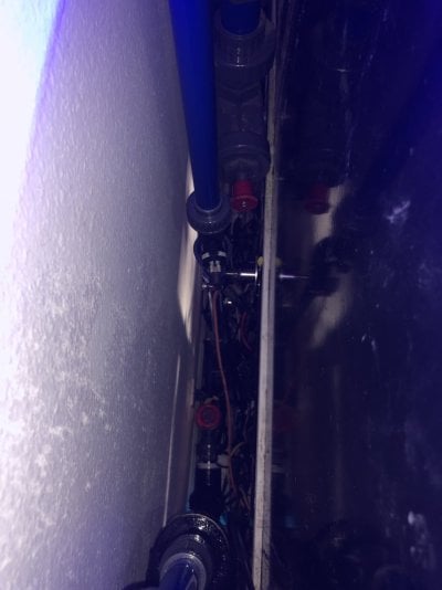
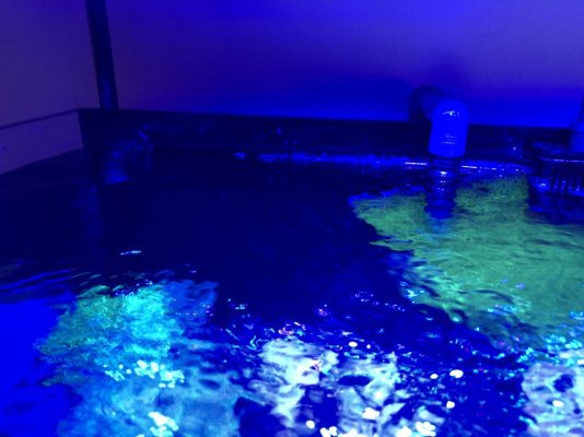
Goal - To Run a Closed Loop in Display Tank - without dedicated CL holes drilled- Checking in with all of you expert plumbers - All ideas welcome TIA!
IDEAS:
1) Running a intake & return line over the back of my tank to feed the UV, running the pump externally. Not ideal, but I am in a pickle at this point in the game. Thinking it would have to be 1" pipe to reach my GPH 1050 goal with head loss
2) Combining my 2 return pumps to return at the same 3/4" return display bulkhead. This would achieve opening up a 3/4" Bulkhead for partial possible closed loop UV application. Thinking this would be possible given that my sump runs around 300gph, and a single 3/4" bulkhead could handle that. I understand that running 2 pumps into the same bulkhead return would require some extra plumbing check valves etc.
3) This is getting kinda crazy, but thinking of using the Emergency external overflow bulkhead as an intake for the UV closed loop. My external overflow has 3 11/2" drains. All go to the sump, all are open 11/2 PVC. First main overflow drain goes to my filter roller thru a valve. The second overflow hole is open 11/2 at top, and only get overflow water if first drain/valve out of adjsutment. The third hole has a taller 11/2" pipe that has never seen water in 2 years, I cant see how it would be possible to actually need this emergency overflow. --- Now needing 1000gph to feed UV, PLUS, 300gph for sump turnover, that means my 2 tank drilled 11/2" holes feeding the external overflow will be sucking in 1300 gph, yet only 300gph would be actually making it down to my sump.
Current Setup - 150 gallon display - 2 Years running
Goal GPH for my 40watt UV is 1050gph
Qty 2 - 3/4" standard tank drilled holes for return
Qty 2 - 11/2" tank drilled holes for EXTERNAL overflow
External Overflow has Qty 3 - 11/2" holes drains to sump - Max Spec Flow rate is 1600gph
Qty 2 - Return pumps from sump for redundancy, both dedicated return on one side
Both returns on flow sensors - Totaling about 350GPH turnover - my filter roller only handles max 500 gph, so tank sump turnover of arond 300gph is its happy zone. I am happy with this turnover rate as well, my sump is very efficient and I already strugggle maining enough nutruents for my corals.
I have 3 pumps to make this somehow work, all can be run internal or external, 2 for return, 1 for UV - all lines will have flow sensors
Sicce DC Adjustable 1000-2500 gph
Sicce DC Adjustable 400-1600 gph
Sicce Non-Adjustable 1900 gph


