ATO 1-sensor or Min/Max? ATO 2-sensors?

TehBrainz

Well-Known Member
View Badges
Joined
Jul 31, 2018
Messages
719
Reaction score
570
Location
Baltimore, MD
Rating - 0%
0   0   0
What ATO type do you use for ATO functionality with your profilux?

I have run 2 sensors for my AWC on the Maxi 2.2 doser for about a month and just got another sensor to replace my current ATO set-up (Hydor Smart Level Controller).

Sensor 1 (Top) and 2 (Bottom) are used for my AWC and spaced ~2" apart. I added my 3rd sensor (Middle) about 1/2" from Sensor 1 (Top) and set the ATO function to "Min/Max" utilizing Sensor 1 (Top) and 3 (Middle). My only concern is this "removes" my high water alarm that I had on my previous ATO. I do have a run-time alarm turned on.

I'm wondering though if I should use ATO in 1-sensor mode using Sensor 3 (Middle), change AWC to use Sensor 3 and Sensor 2, and use Sensor 1 as the high Alarm. The idea of having 2 failsafe methods makes me more at ease (Run-time alarm on ATO AND Sensor 1 alarm). What I'm not sure of exactly, is how a 1-sensor ATO with a float switch works with the system. There's about 0.5" movement in the float, is that the change in sump level during an ATO event?

Does anyone have any thoughts?
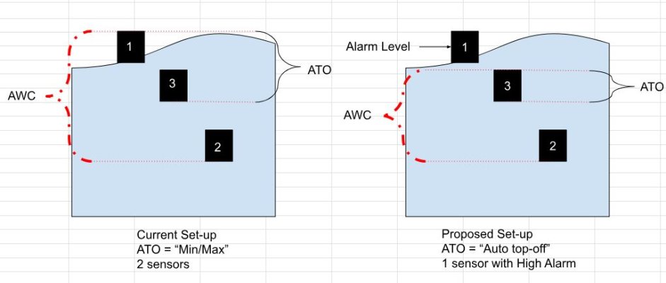

ATO Design.JPG
 

BeanAnimal

5000 Club Member
View Badges
Joined
Jul 16, 2009
Messages
5,071
Reaction score
8,108
Rating - 0%
0   0   0
What ATO type do you use for ATO functionality with your profilux?

I have run 2 sensors for my AWC on the Maxi 2.2 doser for about a month and just got another sensor to replace my current ATO set-up (Hydor Smart Level Controller).

Sensor 1 (Top) and 2 (Bottom) are used for my AWC and spaced ~2" apart. I added my 3rd sensor (Middle) about 1/2" from Sensor 1 (Top) and set the ATO function to "Min/Max" utilizing Sensor 1 (Top) and 3 (Middle). My only concern is this "removes" my high water alarm that I had on my previous ATO. I do have a run-time alarm turned on.

I'm wondering though if I should use ATO in 1-sensor mode using Sensor 3 (Middle), change AWC to use Sensor 3 and Sensor 2, and use Sensor 1 as the high Alarm. The idea of having 2 failsafe methods makes me more at ease (Run-time alarm on ATO AND Sensor 1 alarm). What I'm not sure of exactly, is how a 1-sensor ATO with a float switch works with the system. There's about 0.5" movement in the float, is that the change in sump level during an ATO event?

Does anyone have any thoughts?


ATO Design.JPG
I use a float valve in the sump and an external container with 2 level sensors (top bottom). The sump has a high water sensor. This way the float valve keep the water level constant and I make RO/DI 10 gallons at a time with automation. The sensor in the sump can be use to shut down the ATO production and other logic items.
 
OP
OP
TehBrainz

TehBrainz

Well-Known Member
View Badges
Joined
Jul 31, 2018
Messages
719
Reaction score
570
Location
Baltimore, MD
Rating - 0%
0   0   0
I use a float valve in the sump and an external container with 2 level sensors (top bottom). The sump has a high water sensor. This way the float valve keep the water level constant and I make RO/DI 10 gallons at a time with automation. The sensor in the sump can be use to shut down the ATO production and other logic items.
My container can't be elevated otherwise I'd do something similar. Nothing beats gravity assist.

So the high sensor you're using is only tripped as a failsafe in regards to the ATO production?

I feel having multiple failsafes in this hobby is always a good thing, but I'm not sure if I need 2 with my current setup. At most I'd dump 15g in a ~230g total volume system which would equate to a salinity reduction of ~2 or 3 ppt (35-->32.8). That's assuming it would be dumped the day I filled my reservoir also.
 

Lasse

10K Club member
View Badges
Joined
Mar 20, 2016
Messages
11,262
Reaction score
30,666
Location
Källarliden 14 D Bohus, Sweden
Rating - 0%
0   0   0
There's about 0.5" movement in the float, is that the change in sump level during an ATO event?
No - the change in the sump level is much lesser than that. My sump have the area of 5.25 dm x2.25 dm. My average ATO from my pump in a high/low cycle is 180 ml or 0.18 L = 0.18 dm³ . The math is 0,18 dm³/(5,25 dm*2,25 dm) which give 0.015 dm = 1.5 mm = 0.06"

This is in average

Sincerely Lasse
 
OP
OP
TehBrainz

TehBrainz

Well-Known Member
View Badges
Joined
Jul 31, 2018
Messages
719
Reaction score
570
Location
Baltimore, MD
Rating - 0%
0   0   0
No - the change in the sump level is much lesser than that. My sump have the area of 5.25 dm x2.25 dm. My average ATO from my pump in a high/low cycle is 180 ml or 0.18 L = 0.18 dm³ . The math is 0,18 dm³/(5,25 dm*2,25 dm) which give 0.015 dm = 1.5 mm = 0.06"

This is in average

Sincerely Lasse
My question was a bit confusing due to it being poorly written, apologies.

My question was more geared towards the function of the P4 when using one sensor.

When using just 1 sensor, does the ATO turn on when the sensor is completely in the low position and then turn off when completely in the high position?

Are you using the float or optical sensors in your setup? I'm using float.
 

BeanAnimal

5000 Club Member
View Badges
Joined
Jul 16, 2009
Messages
5,071
Reaction score
8,108
Rating - 0%
0   0   0
I have not looked that the GHL single float implementation but a float switch only has one set of contacts, open or closed. So for 1 switch the pump either short cycles on make/break or there is some hysteresis built in using the switch delay and/or the maximum on time. It is not am ideal setup, but can be made to work and is simple.
 
Last edited:

Lasse

10K Club member
View Badges
Joined
Mar 20, 2016
Messages
11,262
Reaction score
30,666
Location
Källarliden 14 D Bohus, Sweden
Rating - 0%
0   0   0
My question was more geared towards the function of the P4 when using one sensor.

When using just 1 sensor, does the ATO turn on when the sensor is completely in the low position and then turn off when completely in the high position?
And i try to answer that question with no - the on/of movement is only around 1.5 - 2 mm and - yes you need to have a delay on both on and off of about 3 sec. It means that it has to be at on state for 3 sec before it start the pump and at off state for 3 sec before it stop the pump. The floater has an inbuild slack between on and off of about 1.5 - 2 mm I use a single float and my sensor configuration is like this

Overview

1707441295374.png


Main circuit not filling
1707441221053.png

Main filling

1707441512147.png


Overview

1707441383566.png


Sensor circuit when ATO not filling

1707441704547.png


Sensor circuit when ATO filling
1707441556068.png


With other word The on/off slack is around 1,5 to 2 mm (0.06" - 0.08"). My surface move around 1.5 to 2 mm

Sincerely Lasse
 
Last edited:
OP
OP
TehBrainz

TehBrainz

Well-Known Member
View Badges
Joined
Jul 31, 2018
Messages
719
Reaction score
570
Location
Baltimore, MD
Rating - 0%
0   0   0
And i try to answer that question with no - the on/of movement is only around 1.5 - 2 mm and - yes you need to have a delay on both on and off of about 3 sec. It means that it has to be at on state for 3 sec before it start the pump and at off state for 3 sec before it stop the pump. The floater has an inbuild slack between on and off of about 1.5 - 2 mm I use a single float and my sensor configuration is like this

Overview

1707441295374.png


Main circuit not filling
1707441221053.png

Main filling

1707441512147.png


Overview

1707441383566.png


Sensor circuit when ATO not filling

1707441704547.png


Sensor circuit when ATO not filling
1707441556068.png


With other word The on/off slack is around 1,5 to 2 mm (0.06" - 0.08"). My surface move around 1.5 to 2 mm

Sincerely Lasse
Ok great! Thanks for the thorough (as always) explanation.

The delay makes a lot of sense since the float is an on/off signal and you want a constant signal for the ATO to turn on properly. Otherwise, I imagine, the process would wear through some pumps quickly.

I like the idea of having an extra sensor as a failsafe (how many times can I say that word in this thread??) And this can give me that flexibility.
 

BeanAnimal

5000 Club Member
View Badges
Joined
Jul 16, 2009
Messages
5,071
Reaction score
8,108
Rating - 0%
0   0   0
I edited my post - as I stated "it is not a good setup" - and that is not really the case. It is not "ideal" but it is very simple and effective in the right setup.
 

Lasse

10K Club member
View Badges
Joined
Mar 20, 2016
Messages
11,262
Reaction score
30,666
Location
Källarliden 14 D Bohus, Sweden
Rating - 0%
0   0   0
There is a sort of failsafe inbuild in the one sensor circuit. You can set a max time for how long it should be on and after that max time - it make an alarm and shout off the ato pump

Her mine - 7 minutes - black circle

1707481420644.png


Sincerely Lasse
 
OP
OP
TehBrainz

TehBrainz

Well-Known Member
View Badges
Joined
Jul 31, 2018
Messages
719
Reaction score
570
Location
Baltimore, MD
Rating - 0%
0   0   0
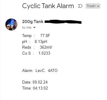
Ok so I have been getting an alarm that I thought I had bypassed. It's not causing anything to stop, but it does spam my texts and email in the middle of the night.

The alarm kicked on ~10-15 minutes from the AWC starting. At this point, the 2 ATO sensors are not engaged and the AWC is still draining to the bottom level sensor. A summary of my AWC and ATO set-ups are below.

My AWC kicks on at specified times controlled by Timer 8 and utilizes Sensor 1 and Sensor 2 for high/low control. Sensor 1 is shared with high level for ATO (highlighted red). Maximum on-time is set to 55 minutes. I've timed the process and it takes on average ~45 minutes. I have operation mode as ATO & water change since I want to turn off the ATO during AWC events. I turned off the "Always active" for Auto top off (ATO) as I found this caused an alarm if Sensor 1 was not triggered.
AWC Circuit.JPG

Timer 8 Schedule
Timer 8 Schedule.JPG

Timer 8 Switch Mode
Timer 8 Switch Mode.JPG


My ATO circuit below. Sensor 1 is the same high sensor as used in my AWC with Sensor 4 (not 3 as I previously posted like a dummy) as my low sensor for ATO. Max on-time is 10 minutes and Always active is turned on.
ATO circuit Overview.JPG

Switch Channel for my ATO
ATO Switch Channel.JPG

Programmable Logic for ATO is below. "Fill water ATO only 4" is for my control circuit 4 utilizing the 2 sensors and water change 2 (inverted) is to turn off my ATO when control circuit 2 (my AWC) is turned on by Timer 8. Logic 7, 8, and 9 tie my ATO to feeding and maintenance events that are not impacted by the AWC and ATO events.
Programmable Logic for ATO.JPG


edited to add Alarm:
Alarm.JPG
 
Last edited:

BeanAnimal

5000 Club Member
View Badges
Joined
Jul 16, 2009
Messages
5,071
Reaction score
8,108
Rating - 0%
0   0   0
Your ATO and your AWC are on the same timer and sharing a float. So maybe the "ATO now" logic is preceding the "NO ATO WHEN AWC" logic and throwing an alarm even though it is working?

You have a lot going on there and I would need to work it out on a piece of paper and truth table later. Have you done that?
 
OP
OP
TehBrainz

TehBrainz

Well-Known Member
View Badges
Joined
Jul 31, 2018
Messages
719
Reaction score
570
Location
Baltimore, MD
Rating - 0%
0   0   0
Your ATO and your AWC are on the same timer and sharing a float. So maybe the "ATO now" logic is preceding the "NO ATO WHEN AWC" logic and throwing an alarm even though it is working?

You have a lot going on there and I would need to work it out on a piece of paper and truth table later. Have you done that?
I dont have my ATO on a timer though, unless the "ATO & water change" function for my AWC forces that to happen. I was under the understanding that I needed that functionality in order to subdue the ATO. Perhaps if I use just the programmable logic and put my AWC on just "water change" it will not give me those errors. I'll test when I get home.

I sketched out the logic when I first set up the AWC a month ago, but I ran through it in my head after changing it for the new ATO and it "made sense" haha
 

BeanAnimal

5000 Club Member
View Badges
Joined
Jul 16, 2009
Messages
5,071
Reaction score
8,108
Rating - 0%
0   0   0
I have honestly not read the manual in regard to that functionality. I will take a look when I get a chance. You may be correct in the way you describe how it should work.

I would think though, that you could set up the ATO on a logic not to run when the AWC time window is open. At least it would give you possible insight into what is triggering the alarm.
 
OP
OP
TehBrainz

TehBrainz

Well-Known Member
View Badges
Joined
Jul 31, 2018
Messages
719
Reaction score
570
Location
Baltimore, MD
Rating - 0%
0   0   0
Yea I'll need to reread the manual myself.

From a functionality standpoint, both the ATO and AWC work as they should. I just get the single ATO alarm each time the AWC runs
 
OP
OP
TehBrainz

TehBrainz

Well-Known Member
View Badges
Joined
Jul 31, 2018
Messages
719
Reaction score
570
Location
Baltimore, MD
Rating - 0%
0   0   0
I have honestly not read the manual in regard to that functionality. I will take a look when I get a chance. You may be correct in the way you describe how it should work.

I would think though, that you could set up the ATO on a logic not to run when the AWC time window is open. At least it would give you possible insight into what is triggering the alarm.
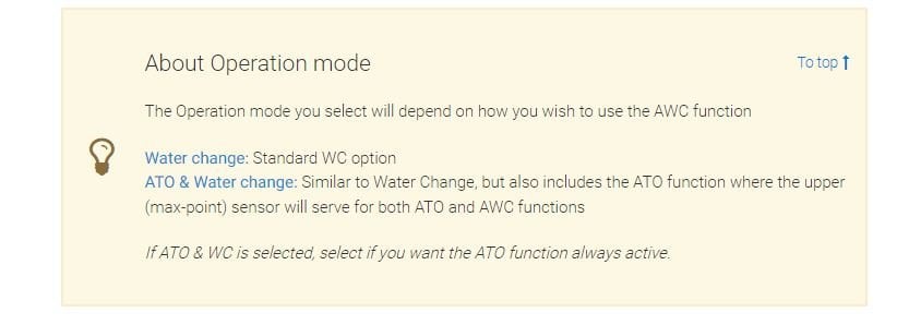
So the manual states the following for AWC operation modes:
GHL manual.JPG

As you mentioned, I believe the "ATO & Water change" mode plus my programmable logic were the conflictions.
  1. AWC would run and by default did initiate the ATO for sensor 1 on Timer 8.
  2. Programmable logic for my ATO does not allow the ATO during the AWC, but the alarm remains regardless.
  3. AWC is complete and the alarm goes away because the float sensors satisfy the alarm states to close.

I switched to "water change" and the ATO section has grayed out. A test will be run shortly, ~45 minutes to get results.
 

BeanAnimal

5000 Club Member
View Badges
Joined
Jul 16, 2009
Messages
5,071
Reaction score
8,108
Rating - 0%
0   0   0
Or you could do the inverse and leave it to AWC adn ATO but remove the additional programmable logic I would thing, as it sounds baked in to the AWC ATO function.

Interested to see what your result is.
 
OP
OP
TehBrainz

TehBrainz

Well-Known Member
View Badges
Joined
Jul 31, 2018
Messages
719
Reaction score
570
Location
Baltimore, MD
Rating - 0%
0   0   0
Or you could do the inverse and leave it to AWC adn ATO but remove the additional programmable logic I would thing, as it sounds baked in to the AWC ATO function.

Interested to see what your result is.
That's true too. I had to have that programmable logic before due to the specific ATO I had not playing well with an external controller. The socket was always "on" and that ATO controlled the pump. So I had to have the logic to physicslly turn off the socket or else it would run. This just being float sensors and all in the GHL control should be aligned with the original intent of the operation modes. I'll test both scenarios...for science!
 
OP
OP
TehBrainz

TehBrainz

Well-Known Member
View Badges
Joined
Jul 31, 2018
Messages
719
Reaction score
570
Location
Baltimore, MD
Rating - 0%
0   0   0
Interested to see what your result is.
Results are in.

I performed a number of settings changes between the way my AWC circuit, ATO circuit, programmable logic, and even Timers were set up.

In short, I was able to keep the ATO alarm off and keep the ATO off ONLY by setting a separate Timer that would keep the ATO off during the AWC timeframe.

Setting AWC to "ATO & water change", having the ATO (within AWC) as "Always Active", and removing the programmable logic resulted in the ATO extended ON alarm, BUT did not turn on the ATO. Changing AWC to "Water Change" and keeping programmable logic off resulted in ATO turning ON. So the AWC setting does seem to stop the ATO, but not the extended on alarm.

Setting AWC to "ATO & water change" OR "water change", having the ATO circuit as the Timer resulted in no alarm and the ATO did not turn on. When I swapped the ATO settings to "Timer" in the AWC circuit and "Always Active" in the ATO circuit, the alarm turned on and the ATO kicked on. Seems like the ATO circuit takes precedence if it's "Always Active" over the ATO setting within the AWC "ATO & water change" operation mode.


Not sure if this made sense. Unless I'm missing something, it seems like setting a Timer to keep the ATO function on only when an AWC is NOT occurring is the only way to keep the ATO on alarm from engaging. Would be nice for a toggle to disengage alarms during WC's like in the sensors (which still doesn't work for me, btw).

New AWC circuit
New AWC.JPG
New ATO circuit
New ATO.JPG
New Timer for ATO to be on at all times EXCEPT during my scheduled AWC's
ATO Timer.JPG
 

BeanAnimal

5000 Club Member
View Badges
Joined
Jul 16, 2009
Messages
5,071
Reaction score
8,108
Rating - 0%
0   0   0
I think there is a token to mask/ignore certain alarms in email.. but I don't know that it prevents the alarm from being triggered.
 
Back
Top