Post 1
My first marine tank was 90 gallons in Michigan during the mid-1980’s and as much as I loved it, I remember the challenges were endless. That setup lasted two homes and 5 years until the kids reached an age where everything revolved around there activities. Which made the effort to great, so I took it down. Now, many years later, and after making the decision to relocate to central Florida, it seemed like a good time for a new tank.
My research started in late 2019 and once I realized how much has changed, I knew I needed to get up to speed with both the biology and the technology. This is a recap of my journey.
It all started with research and you quickly learn not everything you read or watch on the internet is true. As if I had to say that.
Lesson 1: Learn the difference between those who are:
Lesson 2: The internet is absolutely horrible about letting you know how old the information you’re reading and seeing is.
A search will return everything it can find on a subject. You can watch a video that is 10 years old and not really know it. As some things always remain the same, something like the advancement in biology or equipment is another story. Because this hobby is advancing so fast information that is only a few years old can and at times been proven inaccurate, and sometime by the same people. Think of it as, It was the best at the time but currently there is a better way. So, research a topic by reading or watching more than a few articles / videos.
OK back the the build:
Being how we were relocating I had about a year to research and run some tests of my own. As my career consisted of engineering, product design and fabrication all from CAD layout and CNC, I had the knowledge and the tools to do DIY projects. All my DIY projects start with a detailed CAD design, a bit of FEA analysis to prove it out and then is followed by CNC machine fabrication.
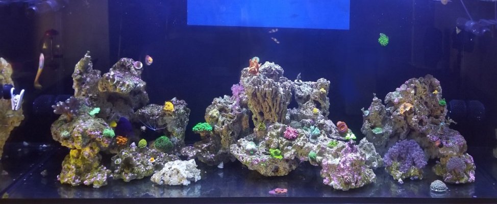
The Tank today is:
Details - When designing the tank stand, I knew I did not want a front center leg or a bulky space consuming construction. I elected steel, based on the near zero center crossmember downward flex at the 60” width. The finished design is 24” deep, 60” width and 36” tall.
CAD DESIGN PHYSICAL BUILD


The tank is an SCA 150-gallon Aquarium rear drilled for a 16” Synergy Shadow Overflow.
I designed a 24” overflow box and machined the acrylic on my CNC. Then assembled it using bulk head fittings


The main and secondary drains pass behind the tank and into my DIY fleece filter roller in the sump.
The roller design is as follows;


The water from the overflow enters the rear of the fleece roller from both the primary and secondary (left and center green drain pipe of pic), the emergency (on the right) empties directly into the sump above the water line.


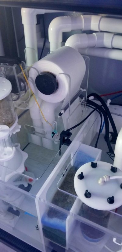
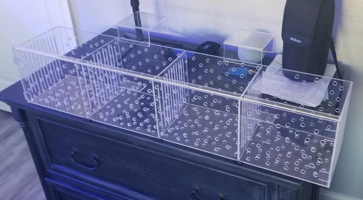
The filter fleece travels inside the acrylic filter panels shown above. Down inside the right panel, across the bottom and back up the left to the take up reel. The nylon threaded rod the hold the front to the rear panel are the guides to keep the fleece traveling against the filter panels. To hold the panels in the proper location there are slots machined on the inside of the front and rear panels.
As the water exits the overflow pipes inside the fleece filter, it must pass through the fleece either to the right, the bottom or the left.
This pic is the front and rear panels with the nylon threaded rods in place. Notice the slot in the front panel. This is the failure overflow. If for some reason the fleece gets clogged from filtering and the float does not trigger the advance the water just flows past the filter and into the sump. The fleece roll advance motor is a 12V geared and high torque, driven by a DIY controller. This rotates the take up reel at 6 rpm.


Here are a few pics of the CNC operation cutting out the Rear panel, one of the fleece filter panel and the final assembly test
How doe it work – As the water passed through the fleece it traps anything and filters it out. This eventually clogs the fleece preventing the water from passing through. When this happens the water level inside the filter rises. Once it hits the high mark it triggers the motor to advance the fleece material. The clean material now in the sump lets the water freely pass thus lowering the water level, and stopping the motor from advancing. The motor will advance until the float drops which disconnects the float switch. The motor then advances and additional 8 seconds. The 8 seconds is so the filter get enough new fleece in the sump to prevent it from advancing to often.
THE SUMP
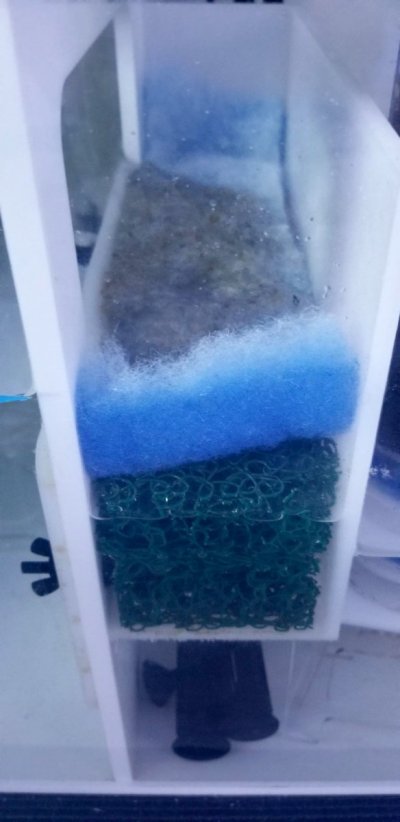
The sump is 48” long 22” front to back and 14” tall. It contains 4 sections. The fleece roller goes behind the skimmer in the first section. As the water fills section 1 it overflows into the bubble trap and then down into the section 2 - one of the pump sections. I have two heaters one in section 1, heating the water in that section and a second one under the bubble trap in section 2 that never really turns on. It is really a backup.

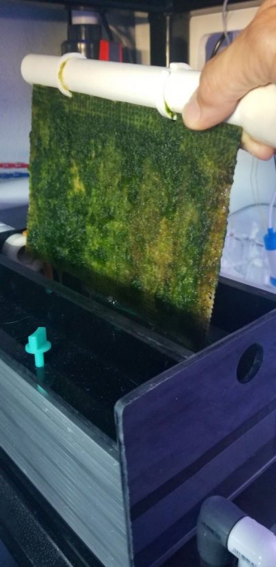
Section 2 has a pump in it and serves the manifold which contains the carbon reactor (not shown) the algae scrubber and the UV sterilizer (not shown) The water then returns from the UV and dumps into section 4. Water that flows through the manifold to the algae scrubber exits straight down the pink pipe and also flows into section 4.
From Section 4 the water passes over the overflow and into section 3 which is were I have the Apex probes and a return pump feeding the display tank. Notice that water can pass between section 2 and 3 behind the pumps. This equalizes the water flow and water level for the ATO. It also prevents intake water from passing through the algae scrubber and the UV more than once.
The pump in section 2 runs much slower (UV sterilized flow rate slower) than the pump in section 3, it is designed for some water get filtered and heated and bypassed pump 1 and flow over into section 3 and into that pump and back to the display.
Also in Section 1 in the rear is where the Neptune Dos draws tank water out and pumps it to a drain. Then in section 2 the same Neptune Dos (line 2) sends new saltwater into the system. This is managed by the Apex Controller. I have also used the rear wall of section 2 to mount the Tunze Osmolator which manages the top off water.
More to Come
My first marine tank was 90 gallons in Michigan during the mid-1980’s and as much as I loved it, I remember the challenges were endless. That setup lasted two homes and 5 years until the kids reached an age where everything revolved around there activities. Which made the effort to great, so I took it down. Now, many years later, and after making the decision to relocate to central Florida, it seemed like a good time for a new tank.
My research started in late 2019 and once I realized how much has changed, I knew I needed to get up to speed with both the biology and the technology. This is a recap of my journey.
It all started with research and you quickly learn not everything you read or watch on the internet is true. As if I had to say that.
Lesson 1: Learn the difference between those who are:
- Publishing quality information based on lessons learned from experience
- Publishing because they think they know what they’re doing
- Publishing just to make a commercial to sell something
Lesson 2: The internet is absolutely horrible about letting you know how old the information you’re reading and seeing is.
A search will return everything it can find on a subject. You can watch a video that is 10 years old and not really know it. As some things always remain the same, something like the advancement in biology or equipment is another story. Because this hobby is advancing so fast information that is only a few years old can and at times been proven inaccurate, and sometime by the same people. Think of it as, It was the best at the time but currently there is a better way. So, research a topic by reading or watching more than a few articles / videos.
OK back the the build:
Being how we were relocating I had about a year to research and run some tests of my own. As my career consisted of engineering, product design and fabrication all from CAD layout and CNC, I had the knowledge and the tools to do DIY projects. All my DIY projects start with a detailed CAD design, a bit of FEA analysis to prove it out and then is followed by CNC machine fabrication.
The Tank today is:
- 150g SCA Aquarium rear drilled for a Synergy 16" Shadow overflow
- Custom welded and powder coated square steel tube stand
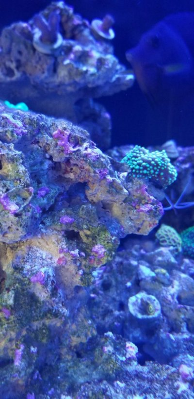
- Bare Bottom tank with a mixture of marco, pukani, fiji, rock for the aqua-scape
- (3 ) Radion XR15 G5 Pro mounted on semi custom brackets from the rear avoiding the euro bracing
- Custom 24" in tank overflow with Bean Animal drain style
- (2) VorTech MP40QD - Mobius Ready QuietDrive
- (2) IceCap 4K Gyre Flow Pump With WiFi Controller
- Custom design 4 section Luna constructed 48x24x14 sump
- DIY 6" Custom Fleece filter roller
- DIY Custom built Carbon reactor
- (2) VarioS-8 Controllable DC Pump (2700 GPH) - Reef Octopus
- SM167 Skimz DC Internal Skimmer
- DIY Custom built Algae Scrubber
- Tunze Osmolator Universal 3155 (ATO)
- Neptune Systems Apex System Controller dual 832 Energy Bars
- Pentair Aquatics SMART 40Watt UV sterilizer
- (2) Innex 75Watt heaters with controllers
Details - When designing the tank stand, I knew I did not want a front center leg or a bulky space consuming construction. I elected steel, based on the near zero center crossmember downward flex at the 60” width. The finished design is 24” deep, 60” width and 36” tall.
CAD DESIGN PHYSICAL BUILD
The tank is an SCA 150-gallon Aquarium rear drilled for a 16” Synergy Shadow Overflow.
I designed a 24” overflow box and machined the acrylic on my CNC. Then assembled it using bulk head fittings
The main and secondary drains pass behind the tank and into my DIY fleece filter roller in the sump.
The roller design is as follows;
The water from the overflow enters the rear of the fleece roller from both the primary and secondary (left and center green drain pipe of pic), the emergency (on the right) empties directly into the sump above the water line.
The filter fleece travels inside the acrylic filter panels shown above. Down inside the right panel, across the bottom and back up the left to the take up reel. The nylon threaded rod the hold the front to the rear panel are the guides to keep the fleece traveling against the filter panels. To hold the panels in the proper location there are slots machined on the inside of the front and rear panels.
As the water exits the overflow pipes inside the fleece filter, it must pass through the fleece either to the right, the bottom or the left.
This pic is the front and rear panels with the nylon threaded rods in place. Notice the slot in the front panel. This is the failure overflow. If for some reason the fleece gets clogged from filtering and the float does not trigger the advance the water just flows past the filter and into the sump. The fleece roll advance motor is a 12V geared and high torque, driven by a DIY controller. This rotates the take up reel at 6 rpm.
Here are a few pics of the CNC operation cutting out the Rear panel, one of the fleece filter panel and the final assembly test
How doe it work – As the water passed through the fleece it traps anything and filters it out. This eventually clogs the fleece preventing the water from passing through. When this happens the water level inside the filter rises. Once it hits the high mark it triggers the motor to advance the fleece material. The clean material now in the sump lets the water freely pass thus lowering the water level, and stopping the motor from advancing. The motor will advance until the float drops which disconnects the float switch. The motor then advances and additional 8 seconds. The 8 seconds is so the filter get enough new fleece in the sump to prevent it from advancing to often.
THE SUMP
The sump is 48” long 22” front to back and 14” tall. It contains 4 sections. The fleece roller goes behind the skimmer in the first section. As the water fills section 1 it overflows into the bubble trap and then down into the section 2 - one of the pump sections. I have two heaters one in section 1, heating the water in that section and a second one under the bubble trap in section 2 that never really turns on. It is really a backup.
Section 2 has a pump in it and serves the manifold which contains the carbon reactor (not shown) the algae scrubber and the UV sterilizer (not shown) The water then returns from the UV and dumps into section 4. Water that flows through the manifold to the algae scrubber exits straight down the pink pipe and also flows into section 4.
From Section 4 the water passes over the overflow and into section 3 which is were I have the Apex probes and a return pump feeding the display tank. Notice that water can pass between section 2 and 3 behind the pumps. This equalizes the water flow and water level for the ATO. It also prevents intake water from passing through the algae scrubber and the UV more than once.
The pump in section 2 runs much slower (UV sterilized flow rate slower) than the pump in section 3, it is designed for some water get filtered and heated and bypassed pump 1 and flow over into section 3 and into that pump and back to the display.
Also in Section 1 in the rear is where the Neptune Dos draws tank water out and pumps it to a drain. Then in section 2 the same Neptune Dos (line 2) sends new saltwater into the system. This is managed by the Apex Controller. I have also used the rear wall of section 2 to mount the Tunze Osmolator which manages the top off water.
More to Come


